Pre Dive Setup (Standard)
Before going to dives, there is some hardware and software setup required to be able to connect to the ROV. The following instructions are derived from the BlueROV2 Documentation in the Blue Robotics documentation, and assume that the BlueROV2 has already been built in accordance to the linked documentation. The Hardware Setup and Software Setup can be completed independently, with the exception of the Motor Direction Configuration.
Physically setting up the GCS (the computer) requires the following steps: connecting the ROV tether to the computer via the Fathom-X interface board; connecting a controller to the computer; and connecting the ROV to power.
The battery needs to be between 12V and 16V to run (assuming the battery is the 4S 14.8 V standard battery provided by Blue Robotics) - it is fully charged at 16V, and should be disconnected from the ROV and charged at 12V. To place the battery within the ROV, unscrew the vent plug shown below to equalize the pressure, and then pull on the plate directly. Place the battery within, connect the end connector to the power connection going to the electronics enclosure, and close the enclosure with the plate again. Screw on the vent plug again.

There are two exposed wire tips coming from the tether, a white one and a blue one (the blue wire has a connector on the tip, the white wire simply has exposed wire at the end) – connect to the green port on the Fathom-X board like shown in the diagram. The board is powered via a 5V Mini USB connection, and can use either a computer USB port for power, or a wall outlet via a USB Charger adapter. Connect an ethernet cord from the interface board either directly, or via a USB-to-Ethernet adapter, to the computer. When power is supplied to the interface board, the PWR LED will light up; if the link between the ROV and the board is working, then the LINK LED will also light up. Note that all the ports on the board are very loose – slight shifting of the board can cause power and data connections to disconnect.

The controller for the ROV is a joystick - Blue Robotics suggests using either a Microsoft Xbox wireless controller or a Logitech F310 controller. The controller used when constructing this repository was a wired Xbox controller.
This is good to download even if QGroundControl is not being used to actually control the ROV, as it provides a nice interface to view the images and change parameter settings.
For Linux, make sure to run sudo chmod to make the AppImage executable. Network Setup: Connecting the ROV to the computer requires the computer to be on the same local network as the onboard Raspberry Pi, and at the correct IP.
Windows (from Blue Robotic's Software Setup manual)
- Go to Control Panel > Network and Sharing Center and then choose “Change adapter settings”.
- Right click on the Ethernet adapter, then choose Properties.
- In the properties dialog, choose Internet Protocol Version 4 (TCP/IPv4), then click Properties.
- Select “Use the following IP address” And enter
192.168.2.1for the IP address and255.255.255.0for the Subnet mask. Then select OK. - Go to Control Panel > Windows Firewall and then select “Allow an app or feature through Windows Firewall”. Select “Change Settings” and then select “Open source ground control app provided by QGroundControl dev team” or “QGroundControl”.
Run sudo ifconfig [name of ethernet connection] inet 192.168.2.1 in the terminal.
The button layout, when using QGroundControl as the ground control, is as seen below (taken from the Blue Robotics documentation):

The motor direction parameters within QGroundControl must be configured prior to operation. Follow the steps in the Hardware Setup to connect the ROV to QGroundControl. Follow the steps listed below to complete the motor configuration:
- Go to the Vehicle Settings page in QGroundControl and select the Motors tab in the sidebar on the left.
- Arm the BlueROV2 by clicking the switch on the page
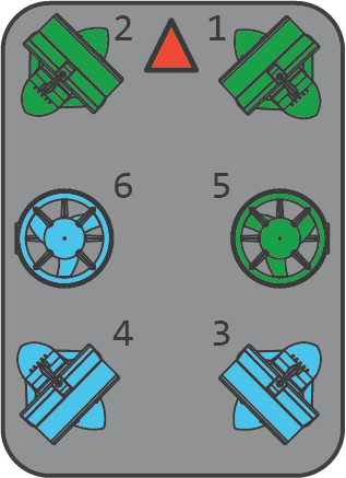
- One at a time, move each slider, and make sure that the motor that spins is pushing air in the correct direction. If a motor is spinning in the wrong direction, click the corresponding checkbox under the ‘Reverse Motor Direction’ section to correct the motor rotation. To more easily detect the direction of airflow, use a strip of paper placed in front of the motor. The correct motor directions are shown below - the front indicating arrow corresponds to the dome of the electronics enclosure.
The joystick's deadband is automatically set at 0 - while the ROV is connected to the GCS, configure this value by going to the Joystick tab, and moving the slider for exponential deadbanding.
When finished with the configuration, disarm the ROV by clicking the switch again.
In the Safety tab, select “Pixhawk Aux6” as the leak detector pin, and set the Logic when dry to “Low.”