
This project focuses on modularity. Each stage is designed to function independently, allowing me to perfect one module and then stack multiple stages to increase velocity. The launcher accelerates a ferromagnetic projectile using a series of these modular stages.
Each module consists of three main components:
- Sensor: Detects the approaching projectile
- Switch: Powers the coil when triggered by the sensor
- Coil: Generates a magnetic field that pulls the projectile forward
The coil is turned off just before the projectile reaches its center to maximize acceleration. If the coil stays on too long, the projectile would be pulled back and forth, ultimately stopping in the center.
Go to /simulator for a detailed physics model and performance analysis.
- Reached a maximum velocity of approximately 12–14 m/s
- Limited by the 2N2222A transistor, which has a maximum collector-emitter voltage of 40 V
- Powered by an 18V Lithium-Ion battery pack, with a max discharge current of ~40 A
| Component | Details |
|---|---|
| Coil Inductance | ~0.750 mH |
| Coil Resistance | 0.45 Ω |
| Number of Turns | 175 |
| Inner Diameter | 12.5 mm |
| Outer Diameter | 35 mm |
| Coil Length | 50 mm |
| Barrel Diameter | 10 mm (carbon fiber tube) |
| Yoke | 1.5 mm iron wire (2 layers) |
| Wire | 1.25 mm enamel copper wire (5 layers) |
| Barrel | Carbon fiber tube (non-conductive, non-magnetic to reduce eddy currents) |
-
Velocity gain per stage decreases over stages, as shown below. This happens because kinetic energy increases with the square of velocity (E ∝ v²), so each additional stage must deliver more energy to achieve the same increase in speed. Additionally, as the object moves faster, it spends less time in each stage, reducing the time, which reduces current and force - further limiting velocity gain.

Velocity vs. stage graph for a 20-stage coilgun powered by a 40 A supply, showing diminishing returns in velocity gain per stage.
/simulator -
Original PCB files were lost — a new PCB design is required to rebuild the system

- Design built-in wire channels between stages
- Use a separate power supply for NMOS driver circuitry to support higher coil voltages
- Apply optimization algorithms (random search, evolutionary techniques) to improve coil geometry
- Add a capacitor bank for higher velocity (at the cost of overall efficiency)
3-stage version @ ~30 V DC
FEMM post-processor output of the coil & projectile

Coil & driver board

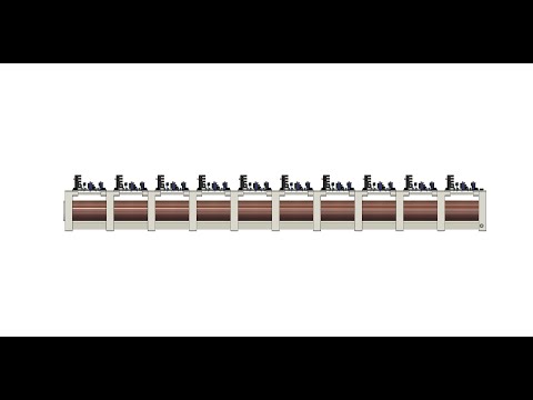
Finished 10-stage version

- A full write-up will be published soon on my website
- A coil geometry optimizer will be created using my existing BLDC motor optimization framework
- Work on Version 2 is planned for 2028 — five years after the original build