Selected experiments using the MSP432P401R SimpleLink™ Microcontroller LaunchPad™ (MSP‑EXP432P401R) to learn about real-time embedded systems. Principles of event-driven systems. Microcontroller organization. Development of embedded applications. Programming external interfaces, programmable timer. Input/output methods: polling, interrupts. Real-time issues: concurrency, mutual exclusion, buffering.
Basic Input/Output (interfacing with LEDs and switches), which will require you to understand the memory map and the relevant definitions and macros, and how to perform bitwise manipulations (setting, clearing and toggling bits).
For the RED LED, there are only two states: on and off. This should be performed through bitwise toggling.
For the RGB LED, there are 8 states, corresponding to off and 7 different colors. This should be performed through bitwise clearing and setting.
In other words, one button changes between the RED LED and the RGB LED: the other button changes the current state of the current LED, allowing us to turn the RED LED on and off and cycle through all the colors of the RGB LED
Button 1 toggles between LEDs. When the button is pressed, the currently selected LED retains its state, and we begin updating the other LED as described below in BEHAVIOR.
Button 2 pauses/resumes the system. When paused, if LEDs were off, they should remain off. If LEDs were on (or in a certain color), they should remain on (or in a certain color). When system resumes, BEHAVIOR continues as if no pause had occurred.
BEHAVIOR: assuming system is not paused, the currently selected LED should switch to the next state every second. E.g., if the Red LED is currently selected, it toggles on and off every second. If the RGB LED is selected, it changes to the next color every second. This has to be implemented with Timer interrupts.
NOTE: when the system is paused, no Timer interrupt should occur.
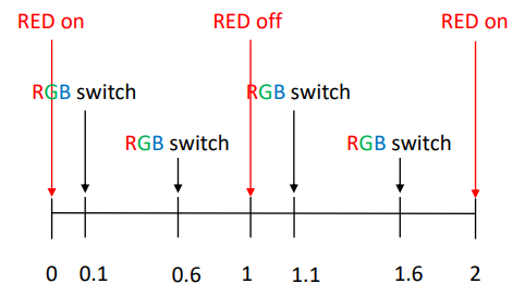
We want one Red LED to blink (on/off) every second, and the second LED (RGB) to blink (change to next color) every 0.5 seconds. The two LEDs should be out of phase by precisely 0.1 seconds (see diagram below). Use TimerA0 in UP mode (and corresponding interrupts) to trigger the RED LED and TimerA1 in UP/DOWN mode (and corresponding interrupts) to trigger the RGB LED.
Thanks to the support of TAs and Instructors during the development of this project.
Copyright disclaimer under section 107 of the Copyright Act 1976, allowance is made for “fair use” for purposes such as criticism, comment, news reporting, teaching, scholarship, education and research.
Fair use is a use permitted by copyright statute that might otherwise be infringing.