Assembly Instructions
You can build the Backwoods Logger yourself, if you know a little about electronics. The total cost for parts is about $30 to $40 USD. The Logger Classic uses all through-hole parts, and can be assembled in an hour or two. The Logger Mini uses all surface-mount parts, and is a bit more challenging to build, but can still be assembled by hand.
- Make or buy the circuit board (PCB). Ask the Backwoods Logger Discussion mailing list if anyone has extra boards available. If not, send the included Gerber files to a PCB prototyping service, and they can manufacture a set of boards for about $25.
- Buy the required parts. The total cost should be around $30 to $40, depending on which version of the Logger you're building. See the official part list for the required parts for each version of the Logger.
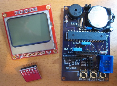
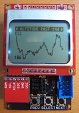
- Add the components to the board, one section at a time: * Power components first. Verify that you get 3V before proceeding. * Microcontroller and ISP header. Verify that you can connect to the ATmega microcontroller using your programming software, and load the Backwoods Logger software onto the device. See the programming guide for more details. * Display screen. Verify that you see text and graphics when power is applied. * BMP085 sensor, buzzer, and other remaining components.
The BMP085 breakout board comes without the header pins attached, so you must solder your own header to it. Solder male header to the same side as the BMP085 chip. When you later mount the breakout board onto the socket on the main board, it should be upside down, with the BMP085 on the underside, hidden from view.
Don't solder the battery holder into place until everything else is built and tested. Use alligator clips or pieces of temporary wire to power the board before the battery holder is in place. Once the battery holder is in, it becomes very difficult to probe or fix solder joints for the adjacent components.
There may be a clearance problem between the battery holder and a few of the surface-mount components closest to it. If necessary, cut away a small portion of the battery holder plastic with a knife to make it fit. Don't cut away any more plastic than necessary, or the battery holder may bend when a battery is inserted.
The BMP085 sensor chip is difficult to hand-solder, because the pins are on its bottom, inaccessible with a soldering iron. The best way to solder it is using a heat gun and solder paste. To solder it with a standard iron, first tin all 8 pads on the PCB with a small amount of solder. Make sure the heights of the solder blobs are as even as possible from pad to pad. Next, apply flux to the BMP085 pins, and place it in position on top of the tinned pads. While pushing down on the chip from above with a pick, heat the exposed portion of each PCB pad, one at a time, until the solder melts. The heat will be conducted along the pad, under the chip, and the molten solder will bond to the hidden BMP085 pin. You may need to repeat this procedure several times to get a good solder connection.
The Eagle .sch and .brd files for the Logger Classic and Mini are included in the project design files. Use these as a starting point for making your own custom Backwoods Logger versions. In addition to the standard Eagle libraries and the Big Mess o' Wires library included with the project, you'll also need the Sparkfun library and Adafruit library.
Piezo buzzer note: The Logger Classic uses a Murata PKM13EPYH4002 piezo buzzer, which has an uncommon 5mm pin spacing. The Logger Classic .sch/.brd files require a modified version of the Sparkfun library that contains this footprint. Your version of the Sparkfun library won't have this footprint, so you'll get an error when opening the schematic or layout file. If you want to use this same buzzer, you can find the appropriate part and footprint in the big-mess-o-wires Eagle library, named PIEZO.