The FaderBuddy is a modular control board for 60mm motorized linear potentiometers, making it simple to add one (or many) to a project with just 2 pins for I2C, plus power!

The control board allows you to read the fader position, move the fader to a specified position, and it can even provide haptic feedback and virtual detents (kind of like a linear version of my SmartKnob project), all easily controlled over an I2C bus from a host controller like an ESP32.
An ESPHome component allows FaderBuddy assemblies to be seamlessly integrated into Home Assistant with just a few lines of yaml!
The onboard ATtiny1616 microcontroller handles all the real-time logic (closed-loop motor control and capacitive touch handling) and provides a simple I2C bus interface - no need to wire a motor driver/H-bridge or implement a PID control loop for each motor fader yourself.
Multiple FaderBuddy boards can be wired together and share just two I2C pins. With right-angle pin headers, you can plug adjacent FaderBuddy boards into each other without any wires for an easy plug-and-play expandable system (supports 18mm or 19mm spacing between faders). STEMMA QT/QWIIC-compatible connectors make it easy to hook FaderBuddy boards to the rest of your design (see wiring diagrams below for examples).

The FaderBuddy community Discord server is the best place to keep up with the latest changes or ask questions about the project!

Learn more about the project and how to build your own below, or purchase a FaderBuddy from the Bezek Labs Etsy store (US-only).
Want to help support development or just say "thanks"? Consider a one-time or monthly sponsorship:
| ❤️ Sponsor scottbez1 on GitHub |
|---|
Using this project in a commercial setting or for paid client work? Go right ahead - it's open source (just make sure to follow the terms of the Apache License including attribution)! I would, however, ask that you consider sponsoring the project. Sponsorships allow me to pay for prototypes and development tools that make this project possible. Unlike pure software projects, every iteration has real hardware costs; sponsorships allow me to keep iterating and improving this and other projects faster. Thank you!
The FaderBuddy integrates seamlessly with ESPHome for Home Assistant automation. The custom component provides:
- Bidirectional (input & output) position sync with Home Assistant entities
- Layer-aware automation triggers (manual_move, touch_change, double_tap)
- Per-layer haptic configuration
- Multiple faders on a single ESP32 via I2C
A simple example looks like:
external_components:
  - source: github://scottbez1/FaderBuddy

fader_buddy:
  - id: my_fader
    on_manual_move:
      then:
        - lambda: |-
            ESP_LOGD("fader", "Fader moved to %d on layer %d", x, layer);
and to move the fader from a lambda:
id(my_fader).remote_move_to(position, layer);That's pretty much all there is to it!
See ABOUT_ESPHOME_INTEGRATION.md for setup instructions and many more examples.
What you need:
- 60mm motorized fader: Behringer MF60T faders (sold in 5-packs as replacement parts) from music/AV retailers like Sweetwater or Amazon - these appear to be manufactured by Soundwell
- FaderBuddy PCB: Available pre-assembled from Bezek Labs in the US (purchasing there directly supports this project), or use the design files fabricate and assemble your own PCBs via JLCPCB. See ABOUT_PCB_FABRICATION.md for details.
- ESP32: Any ESPHome-compatible ESP32 board with 2 free GPIO pins for I2C.
Note
If fabricating your own boards via JLCPCB, you'll also need to flash the firmware before use. See ABOUT_UPDATING_FIRMWARE.md for instructions.
| Pin | Details |
|---|---|
| Vmot | Motor power - 5v recommended |
| Vio | Microcontroller IO power - 3.3v or 5v. This must match the voltage for the SDA/SCL I2C bus! |
| GND | Ground reference |
| SDA | I2C data. FaderBuddy includes a pull-up resistor |
| SCL | I2C clock. FaderBuddy includes a pull-up resistor |
Most common wiring for 3.3v microcontrollers like ESP32: 5 wires from host to FaderBuddy. 5v powers the motor and 3.3v powers the logic.

| HOST | FaderBuddy |
|---|---|
| 5v | Vmot |
| 3.3v | Vio |
| GND | GND |
| SDA | SDA |
| SCL | SCL |
For a microcontroller with a STEMMA QT connector, the FaderBuddy requires an additional 5v wire to power the motor. Additional faders can be chained directly using the pin headers with no extra wires.

| HOST | FaderBuddy |
|---|---|
| STEMMA QT | STEMMA QT |
| 5v | Vmot |
 Alternatively, FaderBuddy boards can be chained using STEMMA QT cables, but an additional 5v wire is also required between each board in that case.
If you have a device that has 5v IO and a 5v STEMMA QT connector (e.g. MCP2221 with the solder jumper bridged to set 5v IO)

| HOST | FaderBuddy |
|---|---|
| STEMMA QT | STEMMA QT |
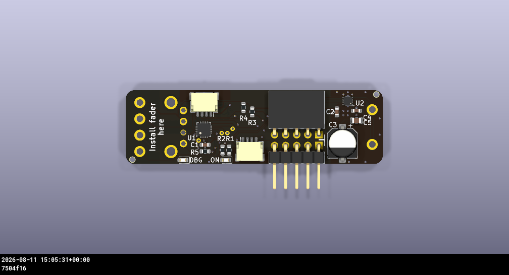
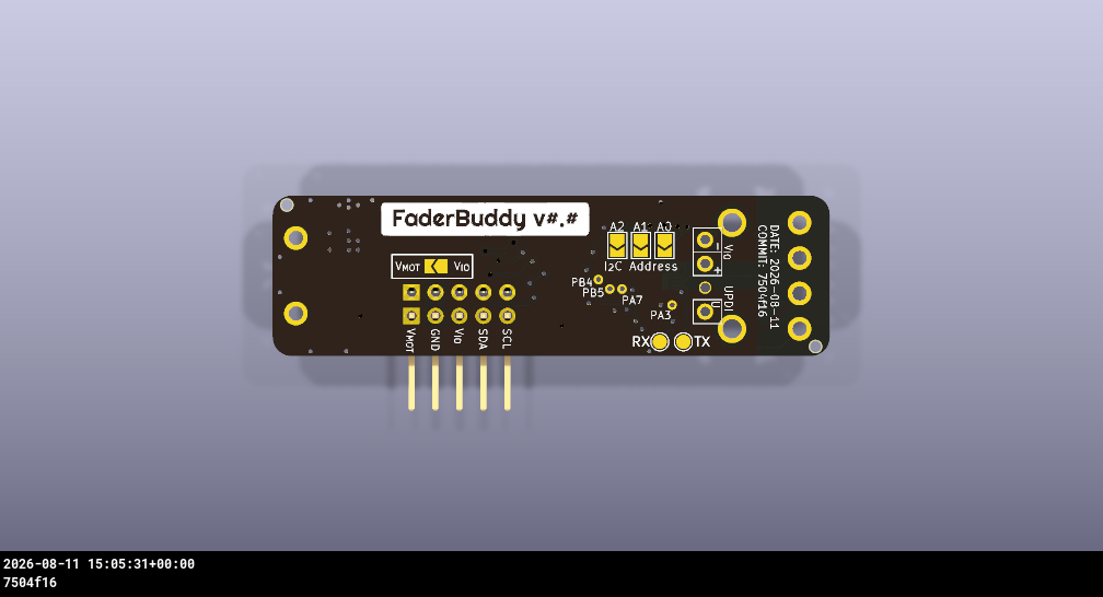
You must also bridge the VMOT ↔ VIO solder bridge on each FaderBuddy so that the 5v IO can be shared with the motor driver.
Be careful when using these solder bridges - if you leave this connection bridged and then later use the FaderBuddy in a 3.3v IO setting, the bridge will connect the 5v VMOT supply to your host 3.3v IO supply which may damage other connected devices!
(Board images attribution: ESP32-C3 supermini image from StudioPieters, MIT Licensed; Adafruit Qt Py and Adafruit MCP2221 images from Adafruit, Creative Commons Attribution/Share-Alike)
By default the FaderBuddy will use I2C address 0x20.
When connecting more than one FaderBuddy to the same I2C bus, or if there's already another device on your bus with that address, the FaderBuddy PCB has 3 solder jumper pads allowing you to change the I2C address by bridging those pads.
| Address | A2 | A1 | A0 |
|---|---|---|---|
0x20 |
[ ] |
[ ] |
[ ] |
0x21 |
[ ] |
[ ] |
[█] |
0x22 |
[ ] |
[█] |
[ ] |
0x23 |
[ ] |
[█] |
[█] |
0x24 |
[█] |
[ ] |
[ ] |
0x25 |
[█] |
[ ] |
[█] |
0x26 |
[█] |
[█] |
[ ] |
0x27 |
[█] |
[█] |
[█] |
The most plug-and-play option (if you're in the US) is to buy the FaderBuddy PCBs pre-assembled from the Bezek Labs store, which come with firmware already flashed, the hardware tested, and it helps support this project and future development!
To fabricate or assemble the PCBs yourself, see ABOUT_PCB_FABRICATION.md for more info on ordering.
Hardware details:
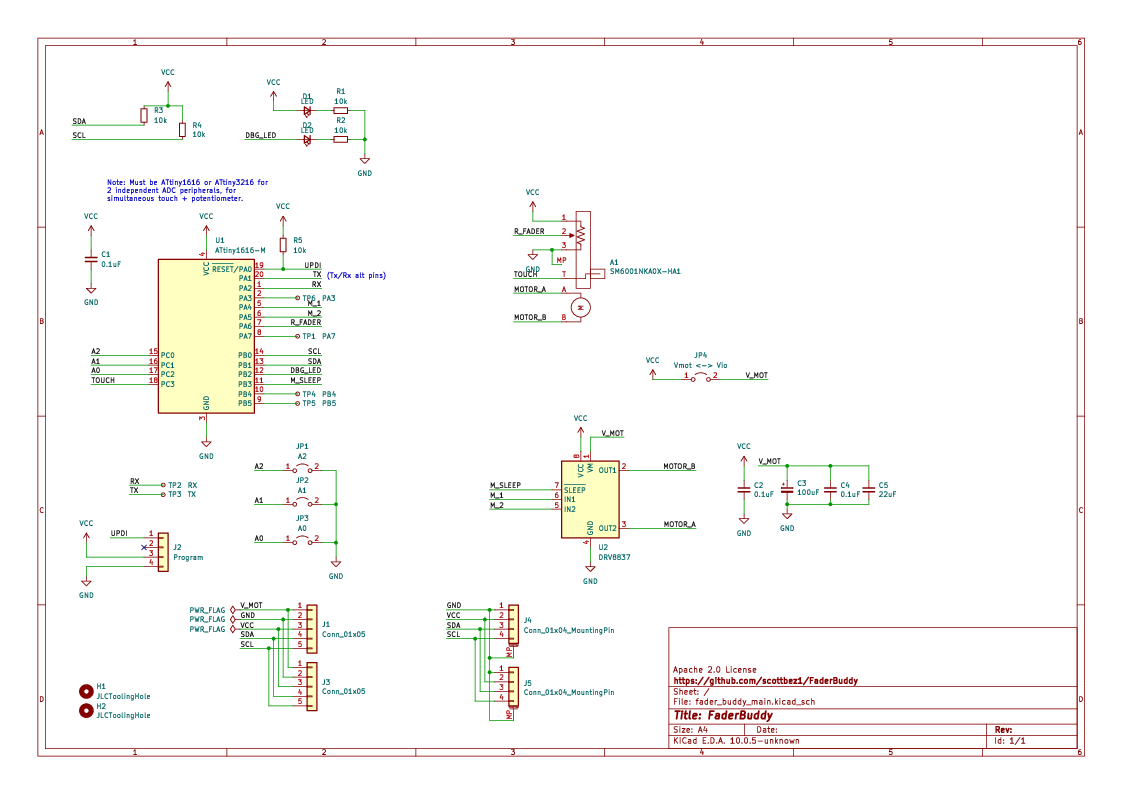
- ATtiny1616 microcontroller with UPDI programming interface
- Supports 3.3v or 5v logic (with 3.3v logic, 5v is still required for powering the motor; with 5v logic Vio and Vmot can be combined for only 4 wires)
- DRV8837 motor driver, with potentiometer position feedback for closed-loop control
- JST connectors for I2C (QWIIC/STEMMA QT-compatible), or 0.1" pin headers for directly chaining adjacent boards
- Capacitive touch sensing for fader touch detection
- Power and debug status LEDs
- Compact PCB design optimized for JLCPCB assembly
You don't need touch capable fader caps - the FaderBuddy will work fine without them - but touch detection allows the FaderBuddy to cancel a motor movement if it detects a touch along the way, preventing the fader from "fighting" against the user. It also allows the FaderBuddy to detect if a user is touching the fader even if they aren't actively moving, and allows you to support a double-tap action on the fader if you'd like.
It's unfortunately nearly impossible to find off-the-shelf mass produced touch-capable fader knobs. Although the Soundwell/Behringer faders use a relatively standard 8mm x 1.2mm fader stem, pretty much all commercially available fader caps are non-conductive plastic and thus do not support touch detection, or are only available as expensive individual replacement parts (oftentimes in used condition).
However, I've found that you can 3D print touch-capable fader caps using conductive PLA filament. Although conductive PLA is generally very high resistance, this is actually a great property for making a touch detection surface.
If you don't want to print your own, you can purchase these 2-color single-piece conductive fader caps in the Bezek Labs store.


The FaderBuddy firmware internally handles the closed loop motor control, presenting a simple I2C interface that can be used to read the position and status of the board, command a movement to a position, and configure haptic feedback. This I2C interface is wrapped up in the ESPHome component, making it a great reference for how to interact with the protocol if you'd like to connect your FaderBuddy to something besides an ESP32 with ESPHome.
- Programmable haptic-feedback modes:
- Smooth operation (no detents)
- Magnetic endpoints (snap to 0% and 100%)
- Configurable detents (1-15 positions)
Configuration of a FaderBuddy supports up to 8 virtual "layers", which allow a single fader to be used for multiple purposes (e.g. controlling lamp brightness and fan speed), with the host controller able to send a single command to switch to a different layer. Switching layers restores the previous fader position for that layer, and will apply that layer's haptic configuration.
See ABOUT_LAYERS.md for more about layers and the I2C protocol.
This README covers the basics, but there are a number of additional pages with more detailed documentation:
- ABOUT_ESPHOME_INTEGRATION.md - ESPHome setup and API reference
- ABOUT_LAYERS.md - Layer architecture and implementation details
- ABOUT_MF60T_LOW_PROFILE_MOD.md - Optional instructions for modifying the MF60T faders so they can fit in smaller areas
- ABOUT_PCB_FABRICATION.md - How to order and assemble your own FaderBuddy boards directly
- ABOUT_UPDATING_FIRMWARE.md - How to upload firmware to the FaderBuddy microcontroller using UPDI
FaderBuddy/
├── electronics/         # KiCad PCB design files
├── firmware/            # ATtiny1616 firmware source (PlatformIO)
├── esphome/             # ESPHome custom component
│   ├── components/      # Component source code
│   └── examples/        # Example configurations
├── software/            # Software tools and demos
│   └── mcp2221-webhid/  # WebHID browser demo tool
├── production_tools/    # ESP32-based production test fixture
└── ci/                  # CI scripts for PCB export
The production_tools/programAndTest directory contains unsupported (source-provided) code for programming and quality control of motor fader boards during production.
FaderBuddy is released under the Apache 2.0 License.
In plain terms: you're free to use, modify, and distribute this project — including in commercial products — as long as you include the license with attribution to this project and indicate any changes you made. You don't have to share your modifications, but you can't claim the original work is yours or use the project name/branding to endorse your product.