DVD Control system is device used by fire brigade to remotly and locally perform actions inside fire station. This version of DVDCS supports remote control by sending simple SMS commands.
For detail information and instructions how to use this device please read the manual.
- Arduino MEGA (joy-it MEGA)
- SIM900 2G Modem
- SD card module
- RTC DS1302
- LCD character display 4 x 20 with I2C module attached
- Matrix Keypad 4 x 4 keys
- Buzzer
- Buttons and resistors (4 pieces)
- Power switch (220V)
- LED used to indicate when modem is ready
- Power supply 5V 3A
- 220V sensor for arduino (DIY)
- Relay array (DIY)
- BUS, two lines of shorted pins used to connect all GNDs and all VCCs together
- Step-up converter used to step-up voltage to 9V so arduino can be powered using Vin pin. (Vin pin is used instead of 5V pin to prevent current flow to computer when connected using USB)
I decided to build few modules myself, since they were either not available or it was significantly cheaper to build them.
This module is used to control other devices connected to DVD control system by switching relays. It consists of relays, transistors and LED indicators, which indicate if relay is turned ON. You can see schematic for this module below.
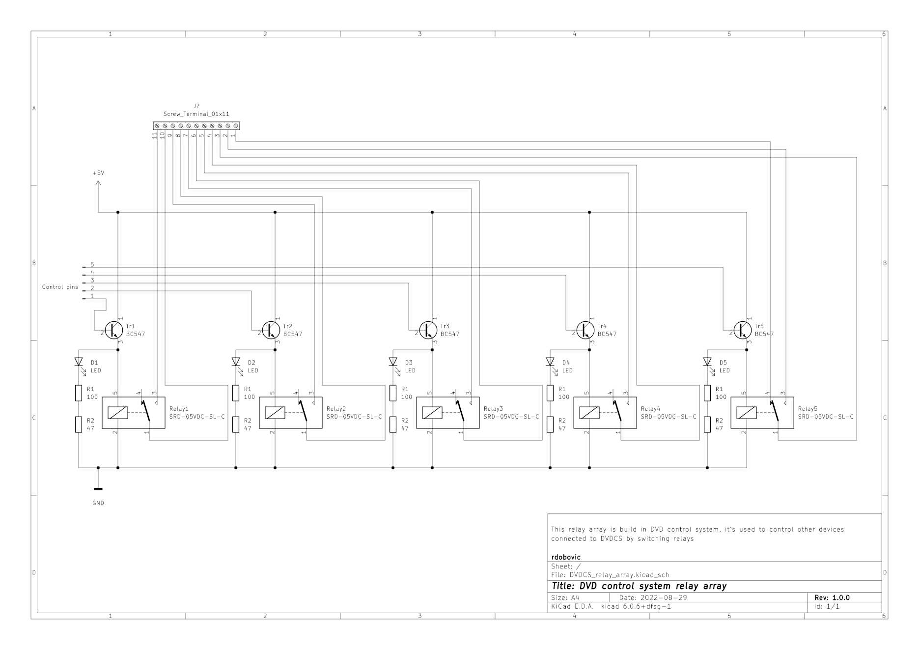
External devices are connected to screw terminal, while Control pins are connected to Arduino MEGA. Connections are specified in intern connections table.
This module is used to detect if light is currently turned ON. 220V input pin, needs to be connected to same power source as light. To separate high and low voltage circuits, when 220V from light is connected to input, LED turns ON, than photo resistor detects that LED is turned ON and logic 1 appears on Data pin. Schematic is displayed below.
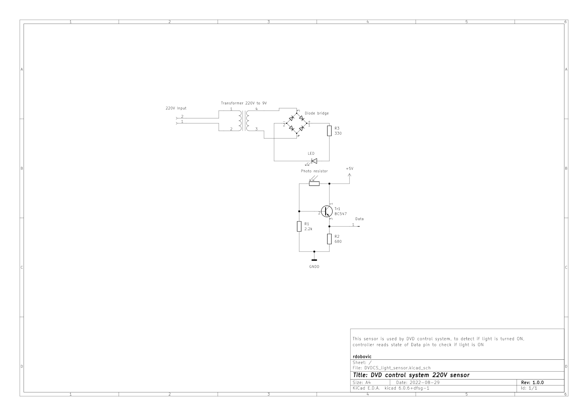
This is probably not the best solution for this problem, but it's good enough for this application. Data pin is connected to Arduino MEGA, so Arduino can read light state.
This is not actually a module, since buttons are not soldered on PCB but connected using wires. I placed this here as reminder how are buttons connected. Buttons schematic is below.
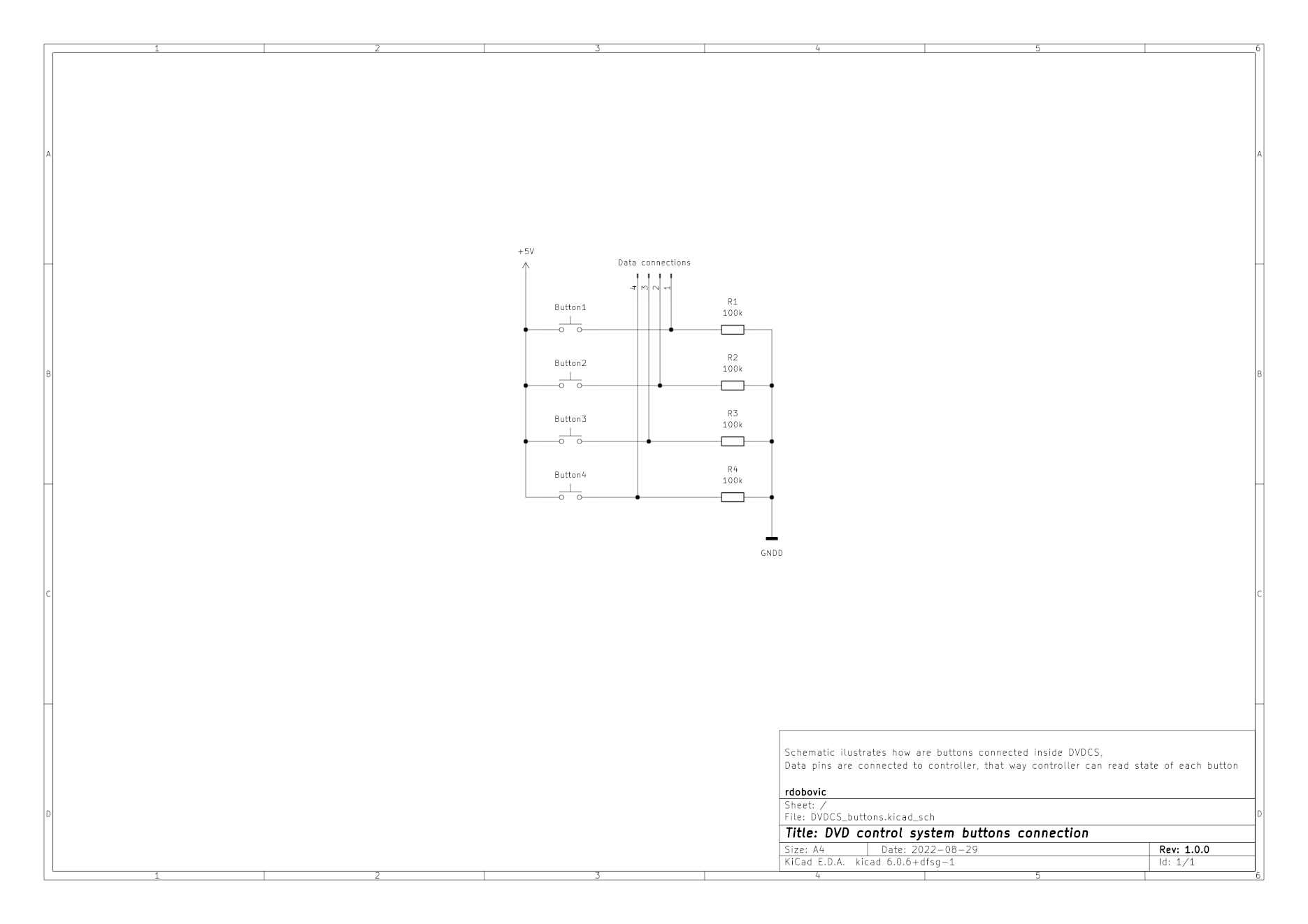
Data connections pins are connected to Arduino MEGA, and used to read state of buttons. There is no schematic for magnet sensors because they are connected in same way as buttons.
Following table describes how is each module connected with Arduino MEGA and BUS.
| Module | Module pin | Arduino MEGA pin | Power BUS |
|---|---|---|---|
| Relay array | 1 | 23 | |
| 2 | 25 | ||
| 3 | 27 | ||
| 4 | 29 | ||
| 5 | 31 | ||
| + | 5V | ||
| - | GND |
| Module | Module pin | Arduino MEGA pin | Power BUS |
|---|---|---|---|
| SIM900 Modem | TX 7 | RX3 15 | |
| RX 8 | TX3 14 | ||
| GND | GND | ||
| 9 | 9 | ||
| Power jack + | 5V | ||
| Power jack - | GND |
| Module | Module pin | Arduino MEGA pin | Power BUS |
|---|---|---|---|
| RTC DS1302 | CLK | 5 | |
| DAT | 4 | ||
| RST | 3 | ||
| VCC | 5V | ||
| GND | GND |
| Module | Module pin | Arduino MEGA pin | Power BUS |
|---|---|---|---|
| Buzzer | S | 7 | |
| - | GND |
| Module | Module pin | Arduino MEGA pin | Power BUS |
|---|---|---|---|
| Buttons | 1 (Neposredana opasnost) | 39 | |
| 2 (Prekid opasnosti) | 37 | ||
| 3 (Vatrogasna uzbuna) | 35 | ||
| 4 (Stop svim uzbunama) | 33 | ||
| VCC | 5V | ||
| GND | GND |
| Module | Module pin | Arduino MEGA pin | Power BUS |
|---|---|---|---|
| Ready indicator LED | + | 8 | |
| - | GND |
| Module | Module pin | Arduino MEGA pin | Power BUS |
|---|---|---|---|
| SD card reader | 3V3 | 3.3V | |
| CS | 53 | ||
| MOSI | 51 | ||
| SCK | 52 | ||
| MISO | 50 | ||
| GND | GND | ||
| 5V | 5V |
| Module | Module pin | Arduino MEGA pin | Power BUS |
|---|---|---|---|
| LCD Display I2C | SDA | SDA 20 | |
| SCL | SCL 21 | ||
| VCC | 5V | ||
| GND | GND |
| Module | Module pin | Arduino MEGA pin | Power BUS |
|---|---|---|---|
| Keypad | 1 | 22 | |
| 2 | 24 | ||
| 3 | 26 | ||
| 4 | 28 | ||
| 5 | 30 | ||
| 6 | 32 | ||
| 7 | 34 | ||
| 8 | 36 |
| Module | Module pin | Arduino MEGA pin | Power BUS |
|---|---|---|---|
| Magnet sensors | 1 (Small door closed) | 41 | |
| 2 (Small door opened) | 43 | ||
| 3 (Big door closed) | 45 | ||
| 4 (Big door opened) | 47 |
Designed and build by rdobovic