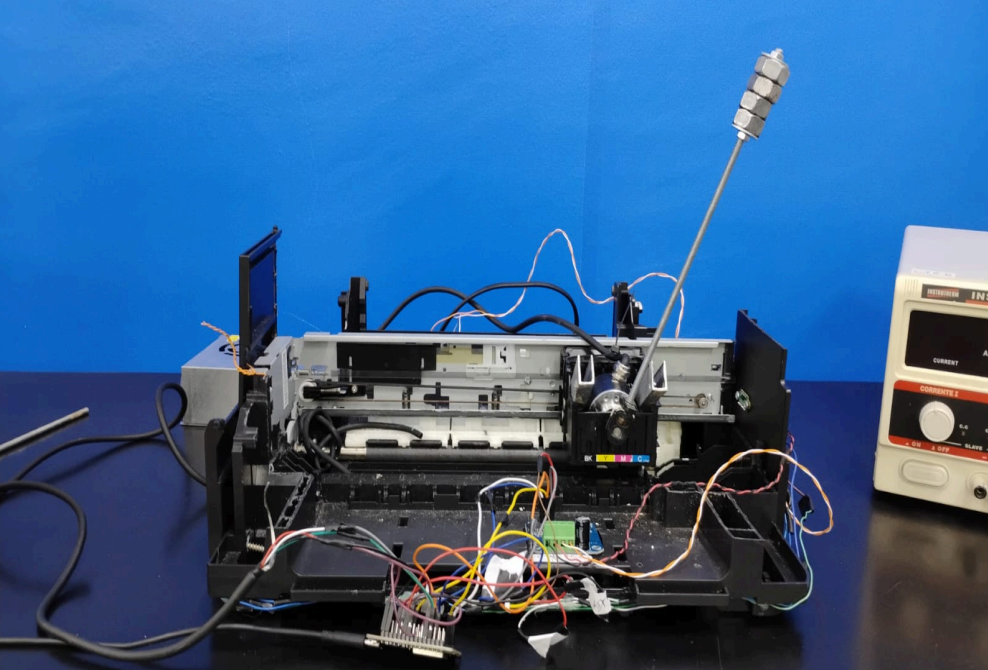
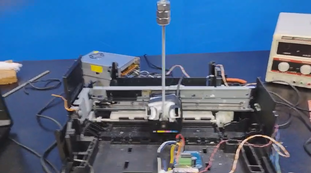
This project consists of the implementation of an inverted pendulum, developed as part of the activities for the Modeling and Control of Systems II course. The base structure was adapted from a regular printer, making use of its built-in 24V motor to drive the rail. In addition to the printer, the following components were used:
| Component | Description | Datasheet |
|---|---|---|
| ESP32 | Microcontroller | 📄 |
| 2 VL53L0X distance sensors | Distance sensor (cart position) | 📄 |
| 360 AB PNP Incremental Encoder (F56) | Angle measurement | 📄 |
| BTS7960 motor driver | DC motor driver | 📄 |
| 24V Bivolt Power Supply - 10A - 240W | Motor power supply | |
| Epson Printer Carriage Motor | 24V motor |
The combination of these components enables the stabilization of the inverted pendulum through real-time control strategies, exploring theoretical concepts applied in the course, which will be presented below.
The main objective of this project is to stabilize an inverted pendulum within a linearized region, keeping its oscillation within a ±10° limit relative to the vertical equilibrium point. To achieve this, system identification techniques will be used, specifically ARX (Auto Regressive with eXogenous input) and ARMAX (Auto Regressive Moving Average with eXogenous input) models, pole placement, and LQR (Linear Quadratic Regulator), in order to:
- Dynamically identify the system from experimental data (ARX / ARMAX), or obtain a mathematical model that adequately represents the pendulum's behavior (pole placement / LQR).
- Design a control strategy based on the estimated model, ensuring stability within the linear range.
- Experimentally validate the controller's performance, analyzing:
- Settling time.
- Robustness to external disturbances.
- Limitations of the linearized model (considering the ±10° constraint).
- Compare the efficiency of the ARX and ARMAX models in representing the system.
Starting from the sensor test code for the BTS7960 H-Bridge, Encoder Angle Sensor, and VL53L0X Distance Sensors, we created a complete code to capture the model's variables, using as reference the mathematical model from Control Tutorials for MATLAB & SIMULINK and the LQR parameters from the GitHub repository we used as a reference. From these variables we built the Pendulum Control code and verified the results through the serial data collector.
KISHAN, I. Inverted Pendulum. GitHub, [S. l.], 2025. Available at: https://github.com/imkishan96/Inverted_Pendulum/tree/master. Accessed: Jun. 3, 2025.
UNIVERSITY OF MICHIGAN. Control Tutorials for MATLAB and Simulink: Inverted Pendulum - System Modeling. [S. l.], 2025. Available at: http://ctms.engin.umich.edu/CTMS/index.php?example=InvertedPendulum§ion=SystemModeling. Accessed: Jun. 3, 2025.
- LinkedIn: Ludmila Anjos
- GitHub: lanjos1
- Email: ludmila.n.anjos@gmail.com
This project was carried out with the collaboration of: Arthur Moreira, Bruno Álamo, Dante Cerqueira, Daphne Soares, Jonathan Sampaio, João Victor Freire, Pedro Braun Pires.