This is an unofficial build guide for the Big Dill Extended rev2. This build has a lot in common with the MurphPad build, and several sections of text have been referenced or directly copied from its build guide for conformity's sake.
It should be said that I have no formal relationship with MechWild. I built my BDE before the official guide was released. This document is only an attempt to describe the steps/resources that I used.
Yours truly, btgrant, aka, BDEGrant
- Soldering iron
- A temperature-controlled iron is recommended.
- Solder wire
- Wire with a rosin or no-clean flux core that is 0.8mm (0.031") or less in diameter is recommended.
- #0 Phillips screwdriver
- A #1 could probably work. Try an eyeglass repair kit screwdriver in a pinch.
- Flush cutters
- Or some other way to trim the diode legs short. Large pliers may gouge the surface of the PCB, so be careful.
The owners of MechWild have assembled a kit of some of the tools they use if you're looking for ideas.
These components are always included with your kit. If any are missing or scuffed, contact MechWild.
There may be extras of some components (diodes, screws, standoffs, etc) just in case.
| Description | Image (if available) |
|---|---|
| 1x PCB | (unavailable) |
| 1x Switch Plate | (unavailable) |
| 1x Bottom Plate | (unavailable) |
| 40x 1N4148 Diodes |  |
| 1x 0.91" I2C OLED & 4x header pins |  |
| 1x Rotary Encoder |  |
| 1x 6x6mm Button |  |
| 1x Encoder Knob |  |
| 8x M2x12mm Standoffs |  |
| 16x M2x4mm Screws |  |
| 4x Rubber Feet |  |
Double-check your order to verify which of these you may or may not have included.
There may be extras of some components (sockets, LEDs, etc) just in case.
| Description | Image | Notes |
|---|---|---|
| 1x Pro Micro & 18x header pins |  |
|
| 1x RGB LED strip (8 LEDs) | (unavailable) | SMD LEDs will not work for this build. |
| 90x 0305 Mill-Max sockets | (unavailable) | Used for making the switches hot-swappable. |
| 90x 7305 Mill-Max sockets | (unavailable) | Used for making the switches hot-swappable. More expensive and more difficult to solder. |
| SIP socket (18x positions) & 18x brass pins |  |
Used to socket the Pro Micro, which makes it removable without desoldering. |
| 1x Diode Bender |  |
Helps you bend multiple diodes at a time consistently. |
Step 1: Program, Test, and Solder Pins on Pro Micro1
💡 If you run into trouble with any of this, don't hesitate to stop by MechWild's Discord and ask for assistance in #keyboard-help. It is much better to triple-check than to have to desolder a Pro Micro!
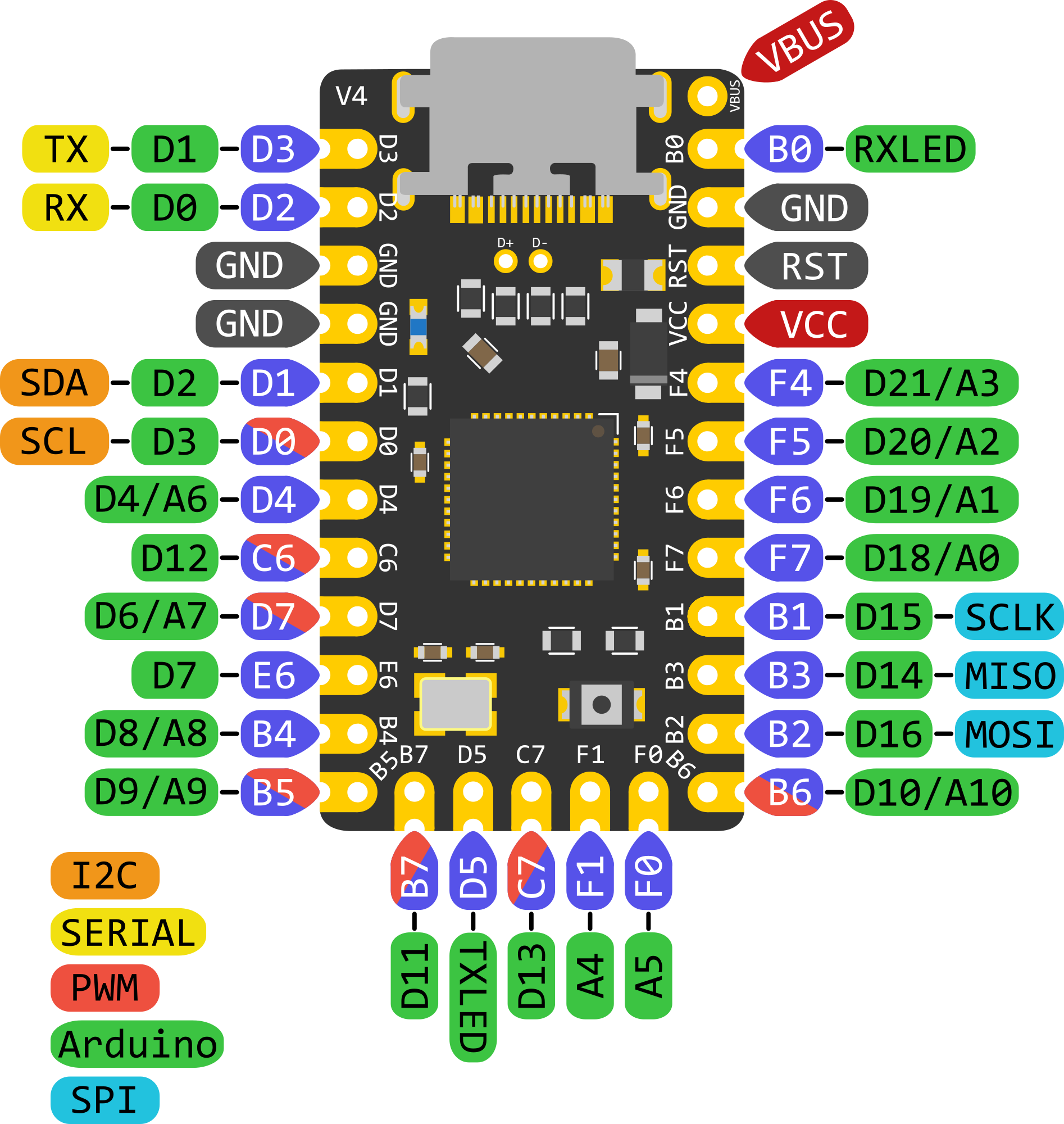
The OLED will not work out of the box on Elite-Cs. Its VCC (power) pin is wired to RAW on a typical Pro Micro. The Elite-C puts B0 in this position instead.
Therefore: if using an Elite-C, do not solder the B0 pin. Solder a wire connecting VBUS or VCC on the Elite-C to VCC on the OLED instead. If using pin headers, breaking off an extra pin so B0 can't accidentally be soldered would be a good idea.2
Don't skip this step; you're only postponing the inevitable, and if it turns out your microcontroller is defective you'll regret it.
When you plug the PM in before flashing, it should show up to your OS as a new device:
| Windows | macOS | Linux |
|---|---|---|
Settings > Bluetooth and other devices |
System Preferences > Bluetooth |
dmesg -w (requires superuser) |
If you don't see anything new here, you may need to try a different cable or USB port.
Recent Vial and VIA firmware builds are downloadable from MechWild's firmware repository.
Firmware can also be generated with QMK Configurator, but Configurator builds will lack features such as dynamic key remapping and matrix testing.
Once the firmware has been downloaded, follow these instructions to program (flash) the Pro Micro.
Note that specific hardware, like a nice!nano, is required to use ZMK firmware. ZMK is not compatible with any 8-bit AVR microcontrollers (Pro Micro, Elite-C, atmega328p, etc).
Once the firmware has been flashed, verify that the Pro Micro now shows up to your computer as a keyboard named BDE Rev2.
If it still shows up as the original device, the flash did not work. If you are using QMK Toolbox, pay close attention to the messages in its console to try and figure out what went wrong. Just because the program says Flash complete does not mean the flash completed successfully!
The guide for preparing the Pro Micro also has images of how it is soldered. Since the microcontroller is attached to the bottom of the PCB, it might look like it is upside down as you install it.
The Visual Guide to Socket a Microcontroller demonstrates the process with the correct orientation.
- Painter's tape or masking tape can be used instead of polyimide ("Kapton") tape.
- The SIP sockets may have been shipped as one long row; break or cut it at the right length.
- Try not to panic if the Pro Micro ends up soldered into the sockets; the keyboard will still work.
Insert the 6x6mm button into the spot marked SW1 on the bottom of the PCB and solder it in place.
Once it is soldered on, you can press this button once to reboot the board, and twice to reset to bootloader for flashing3.
Follow these instructions. Like the reset button, the diodes are inserted on the bottom of the PCB.
Avoid accidentally connecting the metal legs/solder joints of two different diodes. If they aren't kept separate, you may end up with unintentional key presses.
If using pin headers, solder the Pro Micro to the bottom of the PCB just like step 5 of the MurphPad build guide and clip the pins.
If using SIP sockets, feel free to reinsert the Pro Micro if you took it out after soldering the pins in; this is technically optional until step 8.
If you do not have an RGB strip, skip to step 6.
The RGB strip can be attached at any time before soldering switches in—or at any time if you use mill-max sockets to make the board hotswap. However, it is the only part left that attaches to the back of the board and is soldered on the top.
The strip should be wired as follows:
| Red | Green | White |
|---|---|---|
| 5V | RGB Data | GND |
The connector and extra 5V/GND wires can be cut off; they aren't necessary. If the strip doesn't work, cut off the heatshrink to inspect the joints on the strip; it isn't strictly necessary either.
Using the same color scheme the presoldered strip uses is optional, but be sure to solder the wires to the correct end of the strip. The triangular arrow on the strip always points away from the wires.
The 5V, RGB and GND pads aren't labeled on the BDE PCB; this image illustrates which is which.

- If the colored wires are stuck together, peel them far enough apart to work with separately.
- Cut some amount of insulation away from each wire and thread the metal core through the PCB.
- Wire strippers are the intended tool for this job, but a pair of fingernail clippers, scissors, or even flush cutters and a very careful hand can accomplish the same goal.
- If using stranded wire, twist the metal core wires together to make them easier to work with.
Cutting more of the insulation off may make things easier, but make sure the metal parts of different wires do not end up touching each other when soldered onto the PCB and/or strip.
Note that the wires between the PCB and the strip will end up crossing over each other and the central RGB Data wire. This image illustrates a completed, working example:

This is the first part that goes on the top of the PCB. Just like step 6 of the MurphPad build guide:
- Solder the OLED module to the small pin header it was packaged with; if the pin header has one too many pins, break or clip off the extra.
- Pry the plastic spacer off with tweezers.
- Line the OLED module up well, and solder it into place.
- Clip the header pins on top and bottom.
If you are not using an encoder, skip to step 8.
Insert into the top of the PCB and solder. Just like step 7 of the MurphPad build guide. You may need to bend some pins back if they were bent out of place during shipment.
If you didn't already attach the Pro Micro to the PCB in step 4, do it now.
- Plug the board in. If the OLED (and optionally RGB strip) light up, congratulations! 🎉
- Use metal tweezers or a bent paper clip to check each switch position.
- If you used an encoder, twist and press down on it.
Vial and VIA have dedicated matrix testing modes, which take a lot of guesswork out of the testing process. Using them is strongly recommended.
| Program | Screenshot |
|---|---|
| Vial |  |
| VIA |  |
The encoder turn won't show on the matrix, but the press should.
Load QMK Configurator with the expected keymap in one tab and QMK Configurator in test mode in another, and make sure all the keys do what the keymap expects. Keep an eye out for layer keys.
If you did not purchase these sockets, skip to step 10.
- Insert one Mill-Max socket into each switch pin hole. The lip of the socket sits on the top of the PCB, while the rest falls through the hole.
- Place painter's tape, masking tape or polyimide ("Kapton") tape on top of the PCB, to hold the sockets in place while the PCB is upside down.
- Electrical tape will also work, but may leave an unpleasant residue.
- Scotch tape is not recommended.
- Flip the PCB, and solder each socket into place.
- Insert four switches into the top (switch) plate, one in or near each corner. These should click into place.
- Place this plate + switch assembly onto the PCB. Verify all eight switch pins are sticking through the holes in the PCB.
- Continue inserting switches into the plate, making sure both pins on each switch poke through the holes in the PCB. It may be necessary to hold the PCB in place to prevent it from being pushed off, especially in the beginning.
It can be helpful to balance the PCB and plate perpendicular to your work surface, then insert the switches one row at a time. Look down between the two sides to verify pin alignment as each switch is inserted.
If you are not using Mill-Max sockets, you will need to solder the switches after putting them in place.
If positions that worked perfectly in [#step-7-plug-in-and-test](step 7) begin misbehaving after switches are inserted, make sure neither of the switch pins were accidentally bent against the PCB instead of going through the holes. This is more common with Mill-Max sockets as they are harder to align.
Like the Mercutio, the BDE Rev2 uses a sandwich mount. The bottom and top plates are screwed together via standoffs, and the PCB hangs from the switches between them. Screw the standoffs onto the bottom plate, then set the plate + PCB assembly on top and add the final screws.
If you flashed with Vial or VIA firmware, you may use those utilities to dynamically remap your keys without having to reflash. Note that the Vial program is backwards-compatible with VIA firmware4, if the VIA browser app is not a reasonable option.
Footnotes
-
More precisely: a Pro Micro pin-compatible microcontroller (e.g. Elite-C, nice!nano). It might not be a Pro Micro per se, but for the sake of simplicity this guide will refer to all microcontrollers of this type as "Pro Micros" or "PMs". ↩ ↩2
-
Theoretically, it might be possible to power the OLED using the
B0pin by modifying the firmware to pull that pin high on boot and keep it that way while the board runs. Testing this workaround is left as an exercise for adventurous readers. The author(s) of this guide and MechWild as a company eschew all responsibility for any such experiments, unless it ends up working perfectly. ↩ -
Note that entering bootloader this way will not clear the EEPROM. This matters if you're trying to reflash because something is messed up. ↩
-
As of Vial 0.6 and VIA 1.3.1. This may not hold true forever. ↩