NOTICE: this is only personal project, you can left message for questions or advise. I am not expert in ESP32 and coding would take time to respond.
if you got good setting on the OV7725 camera, please share for everyone as starting parameter
- latest update
- 2023 Nov.: update the LED location in the frame buffer calculation excel
- 2025 Feb. done the rewrite the code for ESP32, solved the PS5 flickering, and calculation of fish-eye location for TV.
- 2025 Feb.: after the survey of the ESP32 camera support, the official document has noted the ESP32 PCLK for camera can only support upto 8 Mhz, which in usual board can run in 10 Mhz with no issue. => calculate the clock and datasheet info the MAX FPS in 10MHz is 31.225 FPS, which matches my implement of the project. however with higher frequency of PCLK, ESP32 would not able to catch the pixel data correctly. referece of ESP32 camera performance
- DECIDED, transfer the board to ESP32 S3, which support PCLK upto 40 MHz, should be very sufficient for targeting 60 FPS capturing, could able to higher since the OV7725 support max 48 MHz, maybe able to get 120Hz QVGA output.
- Will archive this and start new fork, after the ESP32 S3 board is arrived the tested.
- New fork plan to adopt following
- not yet start NewRemoteSwitch to rc-switch with custom code
- migrating, VS code, platformIO based, with library esp-camera. will get clean repository
- ongoing in test code, brush-up 2 core operation
- done in test code, update senser setup within setup menu without editing on original ov7725.c, for clear understanding
- done in test code, change base image from QVGA to QQVGA, for LED strip RGB data, and save process image data size
- done in test code, change image buffer to array, easier access through standard thinking
- concept, wire GPIO 33 to selective VCC pin on ESP32 for relay control. Which can cut the power OFF current consumption of LED strip
- 2023 Nov.: update the LED location in the frame buffer calculation excel
in order to make the ambiligt with non app installed, currently Arduino base, no considering low power, as mentioned by @pierre-muth/OV7725_ESP32cam The OV7725 is a more sensitive sensor compare to the one usually found with the ESP32cam board (often the OV2640)
well, in my case I don't need to covnet RGB565 to jpeg for streaming and no need of wifi web server, that saves alot of computing power to achieve 30FPS for single core doing only taking picture by ov7725.
-
when power on, camera is in idle, need to modify the CAPTURE flag to activate at start, or receiving correct IR to activate
-
FPS around 31FPS
- with RGB565, QVGA setting. (can achieve 31FPS without any other tasks)
- ESP32 core 1 main loop for pushing WS2815 data(each image data to LED strip cycle ~10ms) , 433Mhz Tx and IR signal
- ESP32 core 0 handling full power for taking photo and merge RGB565 data for calculation (each cycle ~31ms)
-
the LED location data in the /include/strip_data.h, modify it whenever needed;
- my calculation on the LED location on the image 320*240 try the calculation of mine on /Doc/buffer index_ TFT_xy calculation.xlsx
-
LED light average with previous data, making smooth change over frame to frame, 3 update between frames
-
receive IR signal from ceilling light for activate the movie mode (dim ceilling light + turn on ambilight + strip light of TV deck), turn light off(for alignment of the camera image), and ESP32 sleep mode with turning off all light
-
wake ESP32 cam sleep mode from ext0, activate wake up with IR receiver low signal on GPIO4, still randomly wakeup in the long run
-
RF433 remote control for controlling my RF controlled AC socket connecting to IKEA led strip powering
- the @sui77/rc-switch arduino library is not fit my AC socket controller, there need a variable light contorl available library, is the @1technophile/NewRemoteSwitch
-
AEC, AWB is manual setting for consist color during difference scenes, but the HDR video still has chances got too blueish or less color due to high brightness with no AEC
fully based on my TV set, the image location can only be defined by self calculating on data included /include/strip_data.h, my TV set is 65inch, and 15 cm height and 20cm away from the camera.
Turned off the AEC and AWB for the low light environment of my movie, gaming senario, however there still has color shift in the result, but can modify with the esp32 built in image process function gamma calculation, more detail adjustment can reffer to datasheet of OV7725
with my 65inch TV, need 45 LEDs on right/left side, and 84 LEDs on top/down side, total 258 LEDs by 60 LEDs/meter LED strip, power require ~40W(3.38 A/12V) WLED calculator, however in my real measurement the current consumption is only ~2.5A, measure before adding fuses to the circuit.
- in ESP32cam sleep mode still have 100mA consumption on 12V est it from, (not yet measure new wiring after 2023 Nov)
LCD backlight typ 60mA in datasheet-> added switch in wiring to turn off the backlight when everything settled downcamera standby current 1mA?-> changed the power on state to idle, start capture when correct IR signal appears- LDO 1117 3.3V <10mA
- IR and RF module standby current
- combined above with total est 90% of efficiency of 12V-5V DCDC
- PS5 in high refresh rate will appear unstable light on top, ( camera capture issue from TV top to down) need other mod to deal with it
ESP32-cam clone (using the modified with RST pin, compatible with ESP32-cam MB downloader board)
ov7725 with M12 ~170degree lens ultrawide camera
TFT LCD 320x240 (with ili9341 controlller)
WS2815 248 LEDs for my 65inch TV (depend on the FastLED support)
IR receiver module
RF 433Mhz transmitter module
12V Power supply in my case
fastled/FastLED@^3.5.0
crankyoldgit/IRremoteESP8266@^2.8.5
NewRemoteSwitch-master
bodmer/TFT_eSPI@^2.5.23

 final result

| ESP32CAM pin | wiring to/from |
|---|---|
| 5V | from POWER 5V |
| GND | from POWER GND |
| GPIO12 | to 433MHZ RF TX DATA |
| GPIO13 | to TFT MOSI |
| GPIO15 | to level shift for WS2815 LED DATA |
| GPIO14 | to TFT SCK |
| GPIO2 | to TFT DC |
| GPIO4 | to IR REMOTE RX INPUT |
| GPIO16 | PSRAM #CS pin used |
| GPIO0 | CAMERA used |
| GND(RST) | to TFT Reset pin |
- GPIO 0 is for the camera MCLK generation, connected to camera, which is not suitable for other application once you use camera
- GPIO16 is used for CS# of the PSRAM, which is not suitable for other application once you use camera
- GPIO 1, 3 used for UART communication with PC
- original GND near the flash is modified as RST pin in the clone ESP32-cam board wihcih is useful for pin release
- remove the R13(in reference schematic) 1k resistor or flash to stop the light, flash light is not requried for the application
- still missing one control pin for LCD backlight, GPIO33 is the candidate but it will need solder fix wire for another circuit/ or jumping unused 3.3v/5v pin for GPIO33 connection
click the image for youtube link check the performance by video~
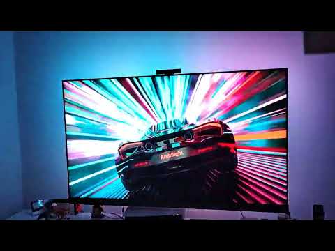

image need to update

notice on the R13 resistor and GND/R pin

 pinout original source
detail pin info can refer
pinout original source
detail pin info can refer
 You can download a PDF file with better resolution on this GitHub repository
 OV7725攝像頭模組模塊 30萬像素 M12鏡頭適用於STM32 OPENMV K210 shop link

| TFT pin | def | wiring to/from |
|---|---|---|
| PIN1 | VCC | TO ESP32 3.3V |
| PIN2 | GND | TO ESP32 GND |
| PIN3 | CS | TO ESP32 GND |
| PIN4 | RESET | TO ESP32 RST |
| PIN5 | DC/RS | TO ESP32 GPIO2 |
| PIN6 | MOSI | TO ESP32 GPIO13 |
| PIN7 | SCK | TO ESP32 GPIO14 |
| PIN8 | BLK | TO ESP32 3.3V |
| PIN9 | MISO | LEAVE OPEN |
can download a related documentation on this site

Regular cheap 433Mhz TX module, with antenna connected for 17.3cm long solid wire, don't use the stranded cable it would not help in the range (google it for detail)
notice, traditional IR receiver module accompany with arduino may not fit with 3.3Vin, find one fit 3.3V operation
notice from the IRremoteESP8266 authorlink
Please have a read of this article and Issue#1173. It appears that the VS1838B is very cheap, and you get exactly what you pay for sometimes. In ideal conditions, you'll get good results, add sunlight/heat etc and it apparently offers poor perforce. We have had similar reports from our users. In short, buy a better hardware IR demodulation device, and your results should improve. If you can't afford the few extra cents, try some of the suggestions offered in Issue#1173.
any type of level shift is okay, typically single direction by transistor is enough no