[FR] (Practical algorithm provided) Vibration compensation #16531
Comments
|
The simulation I wrote can be found at https://github.com/nalimcos/VibComp , along with a copy of the article and a (currently non-functional) gcode postprocessor. I am starting work on a simple proof-of-concept gcode generator, which will print a simple geometric shape over a few layers and could also serve as a calibration tool later on (though of course an accelerometer attached to the print head for auto calibration would be less finicky...) |
|
This seems really interesting and useful, i'll love to help developing/testing. |
|
Yay! EDIT: |
|
First version of the test print generator had a lot of errors, I uploaded a new version a few minutes ago. Here is a little demo, printed at 60mm.s-1, cornering at full speed (marlin 'jerk' set to 120mm.s-1), Tc = 0.007s (see code). /!\ I forgot to specify the correct feedrates for the corrective segments so my comments below must be taken with a grain of salt
EDIT:
|


|
can you share your config.h? ? i'll try printing with the closest settings possible to yours to see if these artifacts on might be software or hardware related, i have some suspicious that jerk and scurve might interfere with it, i got one machine that is pretty solid and has no vibrations until ~130mms (which i never print to be honest), and the other start to appear around 70mms. |
|
scurve and junction deviation are disabled; config.zip Ringing is much less visible on a normal print, the idea here was to voluntarily push the machine to its limits (60mm.s-1 right angles without normal acceleration due to jerk being over 2*feedrate) and show that most of the vibrations could be eliminated. Or did you mean you could print with 130mm.s-1 jerk? |
Usually we have at least two different "spring systems". One is the elasticity of the belts. The other is the possible angle between the rotors static magnetic field and the rotating magnetic field of the coils under load. We also have two masses. That of the rotor and that from the 'sled'. |
For that i prefer the term "jerk-speed" when i talk about Marlins (grbl s) parameter. (Not because this is a exceptional good term, but to differentiate it from "physical jerk") |
That's questionable. If the previous line segment ended with a deceleration phase we already have a displacement. (spring loaded) |
Yes, I was afraid this would be a problem. However, the artefacts I've seen on actual prints show a more simple vibration pattern.
Fair enough. I'm assuming no acceleration (instantaneous target speed changes only) or corrected acceleration (more on that later; but basically, if my more recent calculations are correct, acceleration changes can be treated in pretty much the same way as velocity changes: start at half acceleration during one half of the system's vibration period, then switch to full acceleration.) I wonder whether correction factors would need to change with speed? Not if structure rigidity (a big issue on dirt-cheap Prusa i3 derivatives) or belt elasticity (but I doubt this is often an issue with steel core belts?) is the main issue, but if it's motor torque, then speed will have to be taken into account. |
I use cartesian printers without belts. Only leadscrews. 12mm/turn or 20mm/turn. |
|
Hello! A simple gcode postprocessor is in the works as I'm not quite up to the task of rewriting parts of the planner yet. Slightly held up by a mathematical error somewhere in my code but I'll figure it out :p |
|
Is it possible to use it as a postprocessing plugin for Cura? |
|
I'll have to figure out how that works, I normally use PrusaSlicer. |
|
Well, I have nothing against doing a commercial solution (I personally would be happy to pay), but I'd research the market a little bit more, I'm not so sure many people would be investing in it, as most of the issues regarding vibrations happens on very low cost machines. And for people that probably won't care much
Obter o Outlook para Android<https://aka.ms/ghei36>
…________________________________
From: Milan Cosnefroy <notifications@github.com>
Sent: Tuesday, January 28, 2020 2:23:25 PM
To: MarlinFirmware/Marlin <Marlin@noreply.github.com>
Cc: Italo Soares <italocjs@live.com>; Comment <comment@noreply.github.com>
Subject: Re: [MarlinFirmware/Marlin] [FR] (Practical algorithm provided) Vibration compensation (#16531)
I'll have to figure out how that works, I normally use PrusaSlicer.
A word of warning though, if I am happy with the postprocessor's functionality, I'll publish it as commercial software (with a demo only correcting up to, say, Z=12mm), while leaving all my notes freely available to anyone interested in implementing the algorithm into firmware.
—
You are receiving this because you commented.
Reply to this email directly, view it on GitHub<#16531?email_source=notifications&email_token=ACGQ647RMILLNJSRKBOAYRLRABSY3A5CNFSM4KFPURGKYY3PNVWWK3TUL52HS4DFVREXG43VMVBW63LNMVXHJKTDN5WW2ZLOORPWSZGOEKEFYPA#issuecomment-579361852>, or unsubscribe<https://github.com/notifications/unsubscribe-auth/ACGQ645CPOPHBODSVMLZM5LRABSY3ANCNFSM4KFPURGA>.
|
|
I make saxophone mouthpieces on several different 3d printers: e3d bigbox (converted to top-mounted bowden setup), heavily modified anet e10, anycubic delta with linear rails (with flying extruder)... While they all print very well for most purposes, the tiny bit of ringing I can see even at 20mm.s-1 speed / 5mm.s-1 jerk-speed / 800mm.s-2 acceleration when using a 0.15 or 0.2mm nozzle is more than I like. All in all I have to make this for my own use anyway :) I've fixed the error which was giving me problems BTW, time to handle segments too short for direct correction and I'll be able to start testing! EDIT: simple 'drop segment' solution ready for testing :D |
|
I printed tenor mouthpieces too. But it seems you need refacing in any cases. I hoped I can print exact replicas but failed. Rails are not perfect even at 0.05 layer. Nevetheless I played on one chemically refaced. |
|
Congrats and nice work. The method you are working on is not new though. The idea has been around since the 1950s in the form of Posicast Control. There is a much more elegant and simpler way of doing the same thing. In the firmware, just set the acceleration However, your approach and that described above have a lot of issues that limit their practicality (some of which you've already noted). 1) The system has to be severely under-damped; (2) They are not robust to slight modeling errors; (3) They address only one vibration frequency; (4) They typically force the motion to slow down (or take longer time) to achieve vibration cancellation; and (5) Your particular approach leads to corner rounding and is unlikely to work on short line segments. Input Shaping is another approach that was specifically designed to mitigate some of the issues discussed above. However, it often leads to corner rounding and severe shape distortions. You can visit www.ulendo.io to try a method we've developed to cancel vibration. Using it, we are able to print at high speeds (e.g., 100 mm/s) and accelerations (e.g., 10,000 mm/s^2) without ringing. Again, nice work and great out-of-the-box thinking! |
|
An important point to note is that the X axis is often entirely stationary in the Y and Z direction and so it will only generate ringing in the X direction according to its own independent changes in momentum. And the moving bed will only generate ringing in the Y direction according to its specific momentum. The amount of expected ringing in each dimension will differ according to its mass. If the model is based on an inertial mass supported on an XY gantry with no movement in the bed, the prediction will not match what you get on a system where the X and Y inertial masses are de-coupled, though you can get close by asserting that the two masses are equal. While a certain amount of rigidity in belts and couplings can do a lot to mitigate ringing, the best trick we have in the firmware is the S-Curve Acceleration feature. It doesn't in any way adapt dynamically to the kind of situations I mentioned above, but it can be tuned to a certain point where it covers enough of the gamut. |
|
The 20x faster acceleration (10m/s/s versus 0.5m/s/s) on Ulendo is pretty impressive, though of course the Benchy Groot does display ghost ringing artifacts at that speed. This is understandable given that the Lulzbot TAZ has a pretty massive print head. Now that we've got 32-bit boards that can handle it I do wonder if we could ramp up the acceleration to these kinds of rates with S-Curve Acceleration, and what sort of results we would get. It would be good to explore these limits. |
|
@thinkyhead Thanks for the feedback. Because no compensation is perfect, you are right that there is still a little bit of ringing at 10,000 mm/s^2 but it is less than what we see at 500 mm/s^2. In our whitepaper you can see what happens when we run at 10,000 mm/s^2 without compensation. The ringing is off the charts! I'm glad to see that Marlin has S-curve profiling now. However, while S-curve profiling reduces ringing a bit it does this at the expense of longer printing time. You probably know this already. We have S-curve profiling in Ulendo and it helps a tiny bit but the real benefit in reducing ringing without lengthening printing time comes from vibration compensation. In any case, I'm glad to see concerted effort in tackling the problem of vibration and ringing. It is one of those problems that people can easily avoid by slowing down but they never realize how much they are losing in productivity in the process. This is why I believe that the best solutions to this problem should aim at reducing ringing without sacrificing speed (if possible). That's what we are gunning for. |
|
Indeed we discussed this approach (or an earlier iteration) already in #8071. My conclusion was: Some more details at https://umich.app.box.com/s/n9cvs27ckehdr64gzv5igtmboykymgk6 |
|
You have a very good point. Actually, even high end machines (that cost half a million dollars) that I worked with in industry did not have this type of capability, even though they had severe vibration problems. Our goal with Ulendo is to make it easy for hobbyist machines and industrial machines alike to have easy access to high end algorithms like ours that make a huge difference in performance. In other words, "high end algorithms for all." It's not an easy task but we'll try. We are thinking of creative ways to make the system ID easy and it is looking very promising. Stay tuned. |
In my experience, it can work quite well, but requires a lot of dedication. I use a 0.2mm (or sometimes 0.15mm) nozzle sanded to make the tip as thin as possible, 15-20mm/s speed, a silicone cover for the heatblock; and of course very carefully tuned temperature and fan settings: use the lowest temperature you can get away with, and only then add fan for the tip of the mouthpiece. ==== ProfessorChi , thanks for all the insight! I'll keep an eye on your solution, too.
Now this is a veeeery interesting result :D
This can probably be overcome by applying a greater portion of the required velocity change at the first output velocity change?
In this case, the output moves take exactly as much time as the input moves. This made it easier to synchronize separate per-axis corrections.
Yes, this is where it gets complicated. I did manage to make a working gcode postprocessor with separate corrections for each axis, but it only works on simple large-scale features, and makes a mess of my mouthpieces. I've been trying to figure out either how to pre-process the moves before feeding them to the algorithm... ====
I now do have separate correction factors working, but still have more residual ringing than expected after separate tuning of X and Y correction periods, so I wonder...
I haven't used it yet, I think it was incompatible with something else? I should look into it a bit more. |
Depends on the time of day and position of Mars. |
|
I think this is a great idea, and a relatively easy to implement step on the path to smoother high speed printing. One advantage of this approach is that it never worsens vibrations when choosing bad parameters. In the worst case the vibrations are as bad as before. So the easiest thing would be to chamfer all corners between G1 moves by the same amount. Here is a Matlab script that does this for verbose G-code exported from PrusaSlicer. Sadly I have no printer to test this myself yet. (Waiting for Prusa Mini atm.) To explore the dynamics of different speed/acceleration profiles I created a Jupyter notebook, which you can find here. To simplify the problem I used the following assumptions:
PLOT: X axis model
No deceleration phase PLOTS: No deceleration phase (without damping)

PLOTS: No deceleration phase (with damping)

No Marlin-jerk PLOT: No Marlin-jerk, best case (without damping)
PLOT: No Marlin-jerk, best case (with damping)
The worst case is when the deceleration time is (n + 0.5) times the period: PLOT: No Marlin-jerk, worst case (without damping)
PLOT: No Marlin-jerk, worst case (with damping)
Deceleration phase and Marlin-jerk PLOTS: Deceleration phase and Marlin-jerk (without damping)

PLOTS: Deceleration phase and Marlin-jerk (with damping)

Deceleration without velocity jumps and optimized physical jerk PLOT: Optimized jerk-limited motion (without damping)
PLOT: Optimized jerk-limited motion (with damping)
Sadly this does not work perfectly when the maximum acceleration is not reached. The vibration amplitude depends on the starting velocity. It is quite low, so the extra effort to implement a more complicated solution might be wasted, especially considering the limited accuracy of the dynamic model. I have not calculated the worst case, so it is not exact. PLOT: Short optimized jerk-limited motion, best case (without damping)
PLOT: Short optimized jerk-limited motion, ~worst case (without damping)
PLOT: Short optimized jerk-limited motion, best case (with damping)
PLOT: Short optimized jerk-limited motion, ~worst case (with damping)
Since this concept is much more complicated, starting with theoriginal proposed algorithm seems to be a sensible choice, especially considering the work nalimcos has already put in. I will start a seperate issue for my proposal, when it is ready. But the motion planning with multiple axes and sensible cornering is not trivial, so that may take a bit. My plan is to use my InvenSense MPU-9250 to measure my printer, when I get the printer in june. A breakout board is just a couple of bucks on aliexpress, so hopefully someday most printers will have accelerometers to calibrate the settings, just like bed leveling sensors today. Determinig the first eigenfrequencies for each axis should be doable. (Compared to measuring complete frequency responses as required for #8071.) |
|
@ LSchwerdt, nice work! Your split jerk solution looks like the effect of using the ZV input shaper. Is that what you used? Input shaping is very elegant and easy to implement. It is also very robust. The main problem is that it can lead to severe corner rounding and shape distortions. With regard to measuring complete FRFs, it's not as challenging as you seem to suggest. Having the complete FRF allows one to compensate all servo errors and avoid corner rounding. I really need to get my act together and provide the community with a tutorial on software vibration compensation techniques - together with training on how to easily measure FRFs. I've been thinking of doing this for a while but life just gets in the way. Maybe this summer. |
Splitting the velocity jump this way is just a special case of the corner cutting method proposed by nalimcos. But the paper you linked looks great on first glance. Thanks :)
Measuring FRFs with professional gear is easy. But I expect some challenges when using sensors with milliseconds of delay on a microcontroller with very limited memory. Although I have not really looked into that.
That is definitely the superior solution. But #8071 seems to suggest that simpler methods are preferred for now. Hopefully this changes when/if ulendo can demonstrate good results and gains popularity. And having a good basic motion algorithm is desirable as well, even if it is only for low end printers. |
|
Our paper used high end hardware for measuring FRFs. However, as part of Ulendo, we currently use Raspberry Pi combined with Arduino and two low-cost (ADXL345) accelerometers to measure 3D printer FRFs. I completely agree that simple is better. We tried to implement simple vibration compensation algorithms in Marlin but the fundamental challenge is that Marlin uses displacement-based interpolation instead of time-based interpolation used in higher end controllers. Therefore, we could not implement simple solutions like notch filtering or input shaping. For Ulendo, we completely re-wrote the interpolation to be time-based so we can use notch filtering, input shaping or our FBS algorithm. The corner cutting method is interesting and can work with Marlin, since it is implemented via Gcode, but I see a lot of limitations of trying to implement vibration compensation by corner cutting. However, I'll be the first to cheer anyone that can accomplish it because it would be a simple solution that is compatible with existing firmware. |
|
Klipper does now support something similar to cancel out vibrations: https://www.klipper3d.org/Resonance_Compensation.html |
|
when will we see this feature in marlin? |
Your guess is as good as mine. It's a lot of work and will require a serious effort by a skilled coder. We are open to volunteers, and whoever accomplishes it will be rewarded. |
|
A little update as I log into my github account for the first time in a while... can't really say when, but as I'm now studying computer science and starting work as a software developer, skill won't be the limiting factor anymore. I'll 'just' need the time :) |
|
Hi Everyone, // Recalculate the steps/s^2 acceleration rates, based on the mm/s^2
void Planner::reset_acceleration_rates() {
uint32_t highest_rate = 1;
LOOP_DISTINCT_AXES(i) {
//max_acceleration_steps_per_s2[i] = settings.max_acceleration_mm_per_s2[i] * settings.axis_steps_per_mm[i];//ACT FEEDRATE
max_acceleration_steps_per_s2[i] = (feedrate_mm_s/(3.3/feedrate_mm_s))[i] * settings.axis_steps_per_mm[i];//ACT FEEDRATE
if (TERN1(DISTINCT_E_FACTORS, i < E_AXIS || i == E_AXIS_N(active_extruder)))
NOLESS(highest_rate, max_acceleration_steps_per_s2[i]);
}
acceleration_long_cutoff = 4294967295UL / highest_rate; // 0xFFFFFFFFUL
TERN_(HAS_LINEAR_E_JERK, recalculate_max_e_jerk());
}3.3 is obviously my OScillation rate. Unfortunatly I get:
Does my approach seem logical? Thanks in advance, |
The array subscript at the end |
Thank You so much. It compiled and works. Now I need to test whether it will have an effect on quality |
|
It works great. I have attached a photo of before and after. Both used the same gcode.. Any help is appreciated. I am no programmer and can use any help.. |

|
Well, |
|
max_acceleration_steps_per_s2 is an integer and my calculation is not. Oddly enough it is 46Hz on two very different machines. (I think this 46Hz has some other source but need to find out yet) |
|
I was able to get around the divison by zero problem by putting in 0.021... instead of 1/46. |
|
The way I would go about this would first get some accelerometer module working with Marlin in real time then use that data to get a sense of the problem and how to solve it. Another feature that comes to mind is that one could use accelerometer data to detect run out filament and other clear cases of failed prints. My guess is that there would enough of a change in the vibrations to detect when you are printing on something vs printing on air. Anyway accelerometers are a bit hard to work with because they can generate a lot of data. |
|
@ProfessorChi I understand Ulendo is going to be present at Rapid TCT next month and id love to get a chance to chat! Are you going to be attending? |
|
Yes, I'll be there. I'd love to chat.
…On Thu, Apr 21, 2022 at 12:35 PM InsanityAutomation < ***@***.***> wrote:
@ProfessorChi <https://github.com/ProfessorChi> I understand Ulendo is
going to be present at Rapid TCT next month and id love to get a chance to
chat! Are you going to be attending?
—
Reply to this email directly, view it on GitHub
<#16531 (comment)>,
or unsubscribe
<https://github.com/notifications/unsubscribe-auth/AOUXXQZI2WXQC6VOKZZ37XDVGF7VXANCNFSM4KFPURGA>
.
You are receiving this because you were mentioned.Message ID:
***@***.***>
--
*Chinedum ("Chi") Okwudire, Ph.D. *
*Associate Professor | Mechanical Engineering
<https://me.engin.umich.edu/people/faculty/chinedum-okwudire>*
*Director | Smart and Sustainable Automation Research Lab
<http://s2a-lab.engin.umich.edu/>*
*Personal Pronouns: him/he/his*
--
Office: 2656 G.G. Brown, 2350 Hayward St. | Ann Arbor, MI 48109-2125|
Phone: 734.647.1531
|
|
And im just noticing you are based all of 30 minutes from me! It would definitely make sense to meet up some time, even outside of rapid! |
|
I would love for this to come to Marlin, Its the only reason I left marlin was for klipper to get Input Shaper. Unfortunately I am not a programmer but there has to be someone who is a smart cookie that can figure this out. Its like a feature that I would say most would pay a few dollars for. Thanks so far to OP and others who have got it this far. Lets hope you or others can take it over the finish line. :) |
|
To follow up for those tracking this, we did meet up at Rapid tct and had some good discussion. We do plan to work together and get the time based planner implemented, which is the backbone any vibration compensation relies on. Don't expect their FBS algorithm to be merged in natively, as that is their product being sold and I wouldn't even ask that. |
|
@InsanityAutomation It was great to talk to you at RAPID + TCT. We look forward to working with you to bring in a time-based planner and FBS capabilities into Marlin. I'll be in touch! |
|
Hey folks, I don't suppose there has been any update on this project by any chance? Seems this one is the only project that seems to be focusing on this topic. |
|
232a104 fixed lin advance + s curve combo :) |
|
See #24797 |
|
This issue has been automatically locked since there has not been any recent activity after it was closed. Please open a new issue for related bugs. |
Hello!
'Ringing' (wavy surface pattern) is a common problem when attempting higher printing speeds; vibration compensation has been brought up here before, but this approach seems new, and I believe it would require little enough processing power to comfortably run even on 8-bit controllers.
Quick description
<some math here, check the article for details>
By cutting each corner with an additional segment, along which the speed vector is the average of the speed vector for the previous and next segments, and starting T/4 before reaching the initial corner, and ending T/4 after when it would have been reached (i.e. T/2 after the start of the corrective segment), we can replace the usual oscillation by two waves which cancel each other, resulting in strongly reduced artefacts.
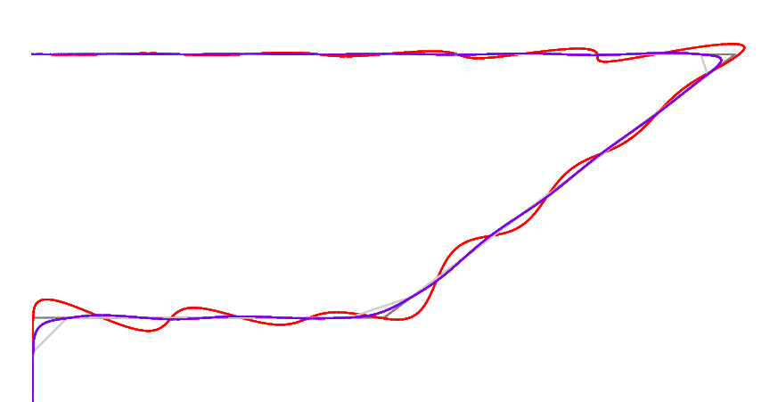
This image was output by a simple simulator I wrote to test my idea.
(No damping in the model leads to a slightly wilder red line and an even better fit of the blue line)
Full explanation with lots of math in attached PDF: vibcomp.pdf . Old work in progress so a bit messy though.
A simple acceleration-induced-vibration correction method as a by-product
While extending this approach to compensate for linear-acceleration-induced vibrations is not as easy, acceleration can be replaced by segments of movement at varying velocities, such that each segment has the duration of half a vibration period of the uncorrected system. Incidentally, this requires much less processing power than even true linear acceleration.
I will add more information and further ideas later on, time for bed here!
Milan
EDIT:
The text was updated successfully, but these errors were encountered: