A project to build a climate controller mounted inside a chicken coop, using a Raspberry Pi Pico's onboard thermal sensors and time-of-year per RTC. For shorthand, this project is referred to throughout the documentation as Cool Chooks Climate Controller, or C4 In its more eloquent form(s), a secondary thermal probe will help validate temperatures are being kept in a stable range; separate SSR's will trigger individual 120VAC outlets, one for the heat lamp for extreme cold and one for a heated water vessel so the chickens don't have to fight ice; servos open/close fan intake/exhaust hatches.
- A Raspberry Pi Pico variant such as:
- Raspberry Pi Pico (standard model)
- Raspberry Pi Pico-W
- Raspberry Pi Pico with WIZNet Ethernet HAT
- WIZNet Pico
- Any other model that still features the RP2040 dual-core processor and GPIO Pins
- UV LED
- Multi-colored LED's (namely white, but include a mix of red, orange, and/or yellow)
- DC-AC Solid State Relay (SSR):
- Activation voltage range must include 3.3VDC
- Work voltage range must include 120VAC
- Fan, 3.3-12VDC
- Heat lamp, 120VAC
- Wire
- 330 Ohm resisters, x?
- Bread-board(s) for mounting components
- Access to a 3D printer (to fab weather-resistant housing(s) for components)
- More fans (for a push-pull arrangement, plus any other air-circulation schemes)
- Many UV LED's
- Relay duplicate(s) (for individually-controlled 120VAC circuits and/or blood-sacrifices)
- RTC module
- External thermal sensor(s) (for additional thermal control points)
- White LED(s) (for illumination in an otherwise dark area)
- A mix of orange, red, and/or yellow LED's
- 100 Ohm resister, x1
- Solenoids and/or stepper motors for actuators to close/open the push/pull hatches
Use the RPi Pico's built-in thermal sensor and internal clock to determine whether the heat lamp and/or fans should be on or off, and to what intensity the UV LED(s) should be set based on time-of-year (more during the winter months, less/none during summer). Use a combination of headers, wires, and breadboards to interconnect all the required hardware.
- Code for the C4 is ... in progress, we'll just say that for now.
- Currently, the main files are boot.py, main.py, and ds1302.py.
- Before "final" production, I intend to add a 4th, tentatively called c4.py, into which all the classes and functions currently in main.py will be moved; this will not only (hopefully) allow for a cleaner file for main.py, but also allow me to manually test functions from the terminal, rather than having to run main.py directly in order to see how the functions shake out. Or if I just want to manually pull sensor data via the terminal while checking logs, etc.
- Code for the ds1302 RTC module (chip, board, & battery) has been pulled from [here][https://github.com/omarbenhamid/micropython-ds1302-rtc/tree/master], but the ds3202.py provided here includes recreated documentation, since the original lacked any in-file documentation whatsoever.
- Contrary to the source's ReadMe file, one does not simply enter the given function commands in order to retrieve an output; you must either assign a variable whose value is equal to the output, and then utilize that, or you must use a print-statement.
- In the brick-meets-skull tier additional functions (which are being migrated to main.py from ds1302.py), the basic breakdown is thus:
- "Day" is any time whose hour is greater-than-or-equal-to 6, and less-than 18 (i.e. 6a.m. and 6p.m.); if an hour-value falls outside that range, it's "Night." This results in an exact 12-12 split and should be sufficient for basic and/or imprecise day/night tracking.
- "Winter" is counted as the entire months of December through February; "Spring" is counted as the entire months of March through May; "Summer" is counted as the entire months of June through August; "Autumn" is counted as the entire months of September through November. Where I am from, this seems a little ridiculous because "Spring" is shrunk down to the second half of April through the first half of May, while "Autumn" doesn't seem to kick-off until at least *mid-*September and ends mid-October unless the snows are late; but I also know some regions basically don't even have winter and summer, just "rain/monsoon" and "dry", so a 25%-25%-25%-25% split of the year between the seasons makes the most "uniform" sense.
- Anything more specific than these, such as "local sunrise/sunset times" or "The First Day of Spring(tm)" will require something much more complex, and robust.
- Some functions do not seem to operate immediately out-of-the-box, meaning that on-going testing and refinement will be required.
- First thing of note is that once a function has been used to return a value, it needs to be "doctored" with modulo (%) in order to produce the correct output (annoying, but fixable during said refinements)
- There is a non-0 chance that during one of the hardware builds, when I put the wires on in the wrong order, I fried something in the chip. I should order more, as well as check inventory for spare parts. Ideally, I source the chip-proper as well as the module boards, because the module boards are a separate failure point.
Using a premade breakout board [like this one][https://www.pishop.us/product/kitronik-pin-breakout-for-the-raspberry-pi-pico/] saves time and helps reduce personal errors, but a potentially cheaper option is to buy 3x7cm protoboards [link warning: Chinese site][https://www.aliexpress.us/item/3256804875486370.html?gatewayAdapt=glo2usa] in bulk (x10 or so) and 20-pin stacking headers [link warning: Chinese site][https://www.aliexpress.us/item/3256805779329126.html?spm=a2g0o.detail.0.0.7fa75ac9umEYNS&gps-id=pcDetailTopMoreOtherSeller&scm=1007.40050.362094.0&scm_id=1007.40050.362094.0&scm-url=1007.40050.362094.0&pvid=80dc169f-b72d-45fe-8cc0-787b800d33aa&_t=gps-id:pcDetailTopMoreOtherSeller,scm-url:1007.40050.362094.0,pvid:80dc169f-b72d-45fe-8cc0-787b800d33aa,tpp_buckets:668%232846%238108%231977&pdp_npi=4%40dis%21USD%210.75%210.53%21%21%210.75%21%21%402101eeda17008040893218215e09f1%2112000035084769008%21rec%21US%214909620431%21], also in-bulk (x20 or so). Whichever one you use is your choice. If you're making your own, it helps to have the male headers already mounted to the Pico (again: prefabbed or DIY), then mount the stacking headers headers to the Pico's headers to help hold them in place, then mount your proto board to that and solder the stacking headers in-place. You then can bend the stacking headers' pins outward so that other devices mounted on the top of the protoboard only need to protrude their mounting holes in order to contact these pins, where they can then be soldered into place. Specifically, you are going to want to ensure there is a dedicated contact for the 5V system pin and a dedicated contact for ground; both the ds1302 module and the accessories board (in later steps) will need access to the VSYS, so if you're using a premade breakout board like the kitronik one above, you will want to either create a splitter that connects to it on one end and provides two different "out" connections, or you will want to use another female stacking header on the Pico so that the accessories board can connect directly to the pico on that and the ds1302 can connect via the breakout board (or visa-versa). For my self-made one, I put a 2x2 male header next to VSYS and the ground at Pin 38, soldered that to the board, then held the stacking header leads for those pins to the respective protrusions and soldered them into place as well. It's up to you whether you leave the remaining ground pins extending out the bottom of the board or cut them off with a flush cutter.
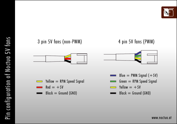
[https://europe1.discourse-cdn.com/arduino/original/4X/a/8/b/a8bd36c195356699119cfc0a6035746bc159f546.jpeg] [https://noctua.at/pub/media/wysiwyg/faqs/noctua_pin_configuration_5v_fans.png]
- Well, I have confirmed through trial and error that a 12V fan will power directly off the Pico's 5V bus, but with only a 3-pin connector on my first guineapig model, there's no controlling the fan speed. (People with tons more experience/knowledge than I do may now commence screaming, "I coulda told you that!" However, being that's an unhelpful comment, I don't care what they say).
- Replacing the fan with [this][Scyth 120mm 12V 4-pin PWM fan][https://www.newegg.com/scythe-su1225fd12mr-rhp-case-fan/p/1YF-0015-000G9?Item=9SIA9ZH8245025] or [this][] model of PWM fan, I've been able to nail down the code for pinning and controlling the fan from a Pico.
- Side note on the scythe fans: these are RGB, with a separate lead for RGB control I desoldered these leads from the fan, rendering them basic fans. Waste of money? Maybe. Did I buy these fans as sacrificial lambs on the altar of trial-and-error/slag-what-may? Absolutely.
- Right now, the fans are being under-powered due to getting only 5V from 5vSys Bus. The plan is to eventually either: a. replace the fan with a Noctua 5V PWM fan b. add a 5v>12V buck converter in between the 5vSys Bus and the 12V fans - Built this; seemingly the amperage to power the 5V->12V buck converter was too much for the system-bus to handle, as the performance was abysmal.
- The deciding factor ultimately will be whether 12V Fans x3 (approx. 0.39Amps) + 5V>12V Buck Converter (approx 1.4Amp capacity) is more or less expensive than Noctua 5V Fans x3 Diagram - Nomenclature - This Build
- Black - Ground/Earth - Purple
- Yellow - +12V power - Red (+5V)
- Green - RPM signal pin - Black
- Blue - +5V PWM signal - White (+3.3V)