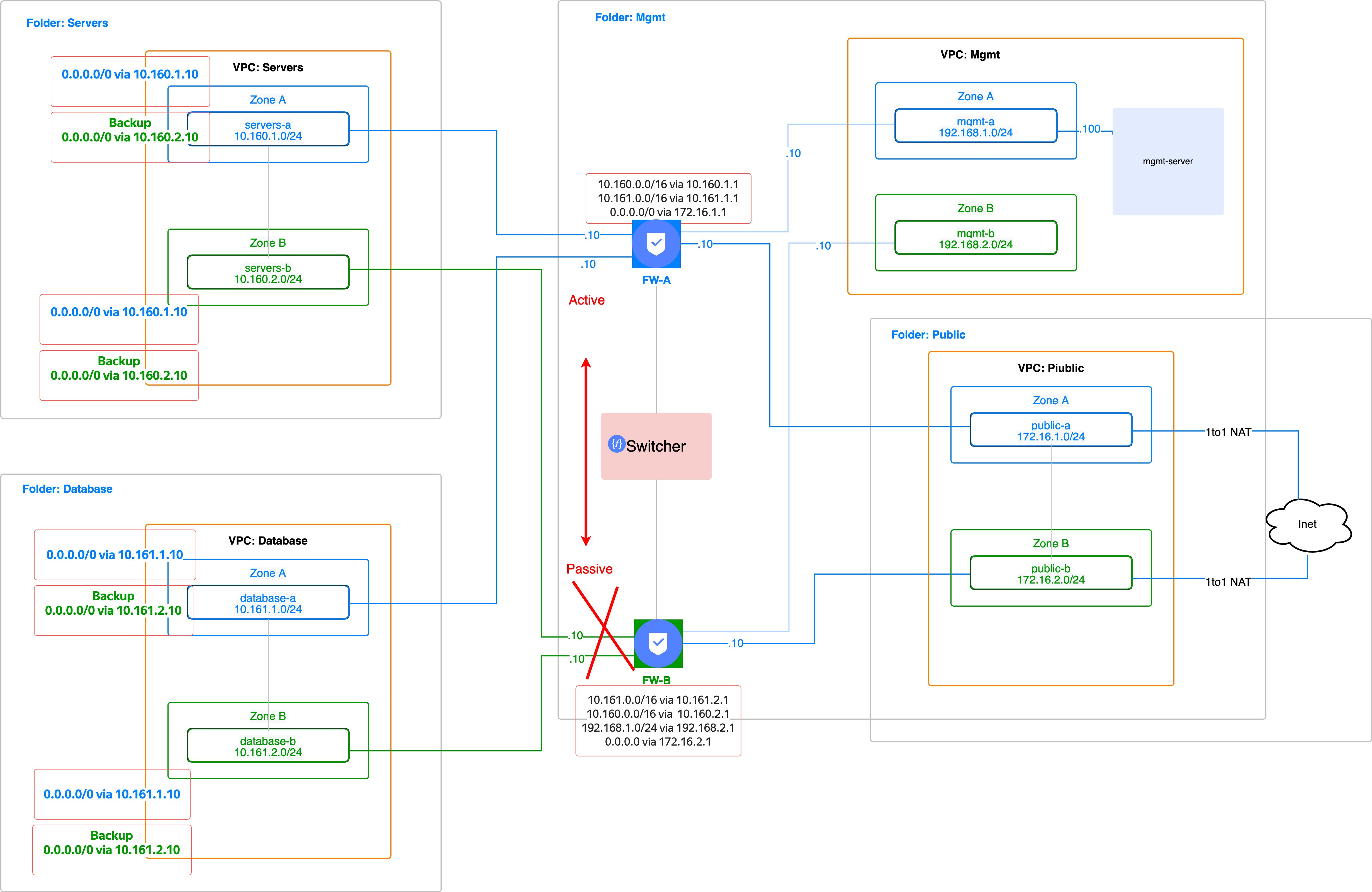
Network segmentation using an NGFW Check Point in two availability zones (DC) in the Active-Passive mode.
Active-Passive means that both firewalls are running, but the traffic is forwarded only to one of them. In case an active FW fails, the passive FW stands in for it. It is performed using Cloud Function and static cloud routes. After the main FW recovers, the solution switches back to the original routing.
- The solution automatically creates several network segments in two availability zones (DC).
- It installs and configures two NGFW Check Points in the Active-Passive mode and the management server.
- Network communication between the zones is still possible and performed without asymmetry.
- If the active FW fails (by default, FW-A is active) connectivity to the Internet and other VPCs is enabled via FW-B.
- The average failure response time for such a solution is one minute, because Cron runs health check scripts once a minute.
- Create a separate folder and VPC for each network segment: Servers, Database, Mgmt, and several VPC-# stubs. Stubs are used because it won't be possible to add more interfaces to the VM afterwards. You can select VPC names at your discretion.
- Create networks and subnets for the VPC data according to the network diagram and the filled out variables.tf file.
- Create the necessary static cloud routes and assign them to VPC subnets.
- ☑️ Create two VMs with a FW: Check Point CloudGuard IaaS - Firewall & Threat Prevention BYOL and one VM instance with the management server: Check Point CloudGuard IaaS - Security Management BYOL. Both images have a trial period. When used in production, FW has a PAYG pay-as-you-go image, and for the management server you need to purchase a separate license from Check Point or use your on-premise license.
- ☑️ Set up FW using cloud-config according to the diagram (interfaces, routes, passwords). That's why you don't need to run the First time wizard.
- ☑️ Create a test Windows machine for managing firewalls using Check Point SMS.
Using the route-switcher.tf file that uses the source yc-route-switcher module:
- Create a Network Load Balancer in the Mgmt folder that checks the state of Mgmt addresses for both NGFWs.
- Create a bucket to store the configuration.
- Create two functions for each VPC: a checker and a switcher.
- The checker cloud function runs a periodic (once per minute) check of the FW status and, if the active FW fails, activates the switcher function.
- The switcher cloud function switches cloud routes so that the traffic from VPCs from both zones is forwarded through the currently active FW.
- ✅ You have an account in Yandex.Cloud.
- ✅ You installed and configured YC CLI.
- ✅ You installed and configured Git.
- ✅ Terraform is installed.
- ✅ An account with cloud administrator's rights.
- Download all the files and go to the folder.
- Fill out the provider.tf file with your
cloud_idandtoken(OAuth token or a service account key file). See details here. - Fill out the variables.tf file. The file contains default values, but you can replace them with your own data (subnets, VPC name, folder name, and so on). Make sure to change the
cloud_idparameter. Example:
//-------------For Terraform

variable "cloud_id" {
  default     = "Your cloud id" #yc config get cloud-id
}
//------------VPC List
//--VPC 1
variable "vpc_name_1" {
  default     = "servers" #choose your name for vpc-1
}

variable "subnet-a_vpc_1" {
  default = "10.160.1.0/24" #change if you need
}
variable "subnet-b_vpc_1" {
  default = "10.161.1.0/24" #change if you need
}
//--VPC 2
variable "vpc_name_2" {
  default     = "database" #choose your name for vpc-2
}

variable "subnet-a_vpc_2" {
  default = "10.160.2.0/24" #change if you need
}
variable "subnet-b_vpc_2" {
  default = "10.161.2.0/24" #change if you need
}
...- Run the command:
terraform init
- Run the command:
terraform apply
- As a result, you will get outputs in the console:
Outputs:

a-external_ip_address_of_win-check-vm = "193.32.218.131" # An address of the Windows VM used for management purposes (log in and download the GUI console from the management server UI)
b-password-for-win-check = <sensitive> # The password for the Windows VM. To get it, run: terraform output b-password-for-win-check
c-ip_address_mgmt-server = "192.168.1.100" # management server IP address
d-ui_console_mgmt-server_password = "admin" # A default password for the management server UI
e-gui_console_mgmt-server_password = <sensitive> # a password to log in to the management server GUI console. To get it, run: terraform output e-gui_console_mgmt-server_password
f-sic-password = <sensitive> # A SIC password for communication between the management server and FW. To get it, run: terraform output f-sic-password
g-ip_address_fw-a = "192.168.1.10" # FW-A address
h-ip_address_fw-b = "192.168.2.10" # FW-B address
i-path_for_private_ssh_key = "./pt_key.pem" # An SSH key to connect to a Check Point VM- Sequence of actions:
- Read all outputs and their values (above).
- Connect to a Windows VM via RDP.
- Connect via the browser to the management server address: enter the default login, password and change the password.
- Download the GUI console from the UI.
- Connect via the GUI to the management server: enter admin as a login, and e-gui_console_mgmt-server_password as a password.
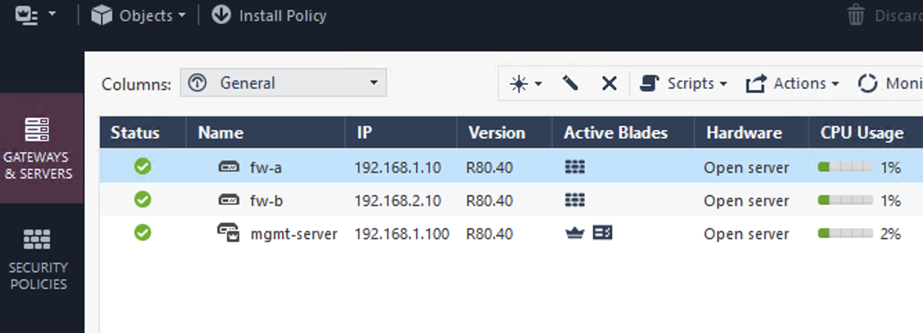
- Add both FWs to the management server using the SIC password.
- Configure antispoofing in the Mgmt interface to allow health checks from the LB: 198.18.235.0/24 and 198.18.248.0/24.
By the results of the test, follow the instructions to ensure security of your infrastructure:
- Be sure to change the passwords that were passed using the metadata service in the check-init...yaml and cloud-int_win...yaml files:
- The password of the Windows VM administrator.
- The password for the GUI console of the management server.
- A SIC password to enable communication between the management server and the FW.
- Save the pt_key.pem SSH key to a secure location or recreate it separately on behalf of Terraform using your bastion tools.
- Delete the public address for the Windows VM.
- Set up ACL and NAT policies in the Check Point NGFW.
- Consider your cloud network specifics and don't assign public addresses using cloud tools to VM instances where the Check Point NGFW is specified as the default gateway. Details are here.
- Select the appropriate license and image: For the FW, either PAYG from the marketplace or BYOL, for the management server — BYOL with its license.
- Deploy the solution using the instructions above.
- Log in to the cloud's UI console.
- Create a jump VM in Zone A in VPC Servers with a public IP address.
- Connect to the VM via SSH.
- Create another VM in the same zone, to run a test without a public address.
- Copy your test SSH key to the jump VM using the command:
scp ~/.ssh/id_rsa alex@62.84.121.175:id_rsa
- Connect to a jump VM via SSH using a public IP address and then via SSH to a VM without a public address.
- Create a VM in the VPC Database.
- Run the command to ping the VM in the VPC Database:
ping <IP address>
- Stop FW-A.
- Check that the ping goes down for a while (about 1 minute).
- Make sure that the ping is back (the traffic has been successfully switched).
- Start FW-A again.
- The ping will again go down for a while (about 1 minute).
- Make sure that the ping is back, and the routing tables are back to their original state.

