Copyright © 2024 Pat Deegan psychogenic.com
How do you get hardware-in-the-loop with cocotb? This is one, perhaps weird, answer to that that allows you to run the very same set of tests, like these:
-
right in an RP2040, like on the tinytapeout demoboards, or any microcontroller that can do micropython;
-
on a Raspberry Pi 5 connected to the DUT;
-
on the desktop, but talking to projects on an FPGA that can be connected to external hardware, over USB; or
-
on the desktop, talking to projects on any external chip, through an FPGA over USB
There are a number of examples available here. The raspi contains examples used on a Raspberry Pi 5, there's also rp2040 and code for use through my FPGA "Simple USB Bridge". The testbench scripts are short, relating only to the particulars of launching the tests on that platform, since all the samples use the same set of tests (which is one of the points of all this), and those are all in common.
So this library will run the same unit tests on an RP2040 and really anything that runs micropython or full Python.
It will also run on the desktop--but then so will cocotb, so what's the point? The point is getting a simplified manner of extending things to talk to real hardware. See simple_usb_bridge for an example of using a USB bridge to an FPGA.
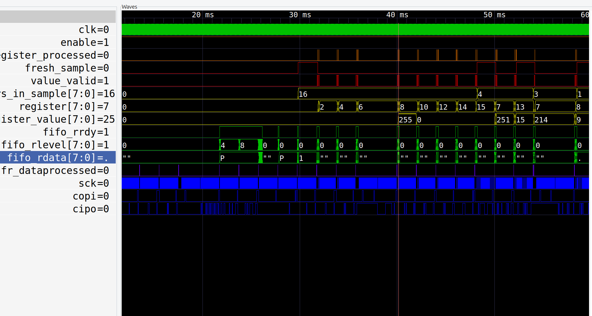
I've used this to get deep inspection VCD waveforms from modules in FPGAs while they run tests and actually interact with external 3rd party hardware, like the SPI flash being read here
I've put up a walkthrough of hardware-in-the-loop testing with cocotb testbenches, showing how to run it using a raspberry Pi 5, an RP2040 and an FPGA, and include some details on inspecting a design's internal signals while it's hooked up to external circuitry:
The backend will do whatever you want--run on the RP2040 directly, or talk over a serial connection or USB or ethernet, etc. Whereas the front end provides a cocotb v2 compatible way to detect and run @cocotb.test() units just like you did during simulation, without modifying them.
You can
-
start multiple clocks
-
have @cocotb.test()s with attributes like skip, expect_error, timeout_*
-
await on ClockCycles, Timer, RisingEdge, FallingEdge
and do most of the usual cocotb things.
One thing it cannot do is inspect internals of an external DUT: when you're only connected to I/O, you can't see what's happening inside and it's a black box. However, one of the use cases, the FPGA tb actually lets you play out in the world but also monitor deep internal state of a design.
For example
@cocotb.test()
async def test_counter(dut):
    dut._log.info("Start")

    clock = Clock(dut.clk, 10, units="us")
    cocotb.start_soon(clock.start())

    dut.ui_in.value = 0b1
    dut.rst_n.value = 0
    await ClockCycles(dut.clk, 10)
    dut.rst_n.value = 1
    await ClockCycles(dut.clk, 1)

    dut._log.info("Testing counter")
    for i in range(256):
        assert dut.uo_out.value == dut.uio_out.value, f"uo_out != uio_out"
        assert int(dut.uo_out.value) == i, f"uio value not incremented correctly {dut.uio_out.value} != {i}"
        await ClockCycles(dut.clk, 1)
    dut._log.info("test_counter passed")

@cocotb.test()
async def test_edge_triggers(dut):
    dut._log.info("Start")

    clock = Clock(dut.clk, 10, units="us")
    cocotb.start_soon(clock.start())

    dut.ui_in.value = 0b1
    dut.rst_n.value = 0
    await ClockCycles(dut.clk, 10)
    dut.rst_n.value = 1
    await ClockCycles(dut.clk, 1)

    dut._log.info(f"Testing counter, waiting on rising edge of bit 5 at {get_sim_time('us')}us")
    await RisingEdge(dut.some_bit)
    dut._log.info(f"Got rising edge, now {get_sim_time('us')}us value is {hex(dut.uo_out.value)}")

    dut._log.info(f"Now await falling edge")
    await FallingEdge(dut.some_bit)
    dut._log.info(f"Got rising edge, now {get_sim_time('us')}us value is {hex(dut.uo_out.value)}")

    dut._log.info("test_edge_triggers passed")
This is from the tiny tapeout factory test design. You'll find more examples in the examples directory there.
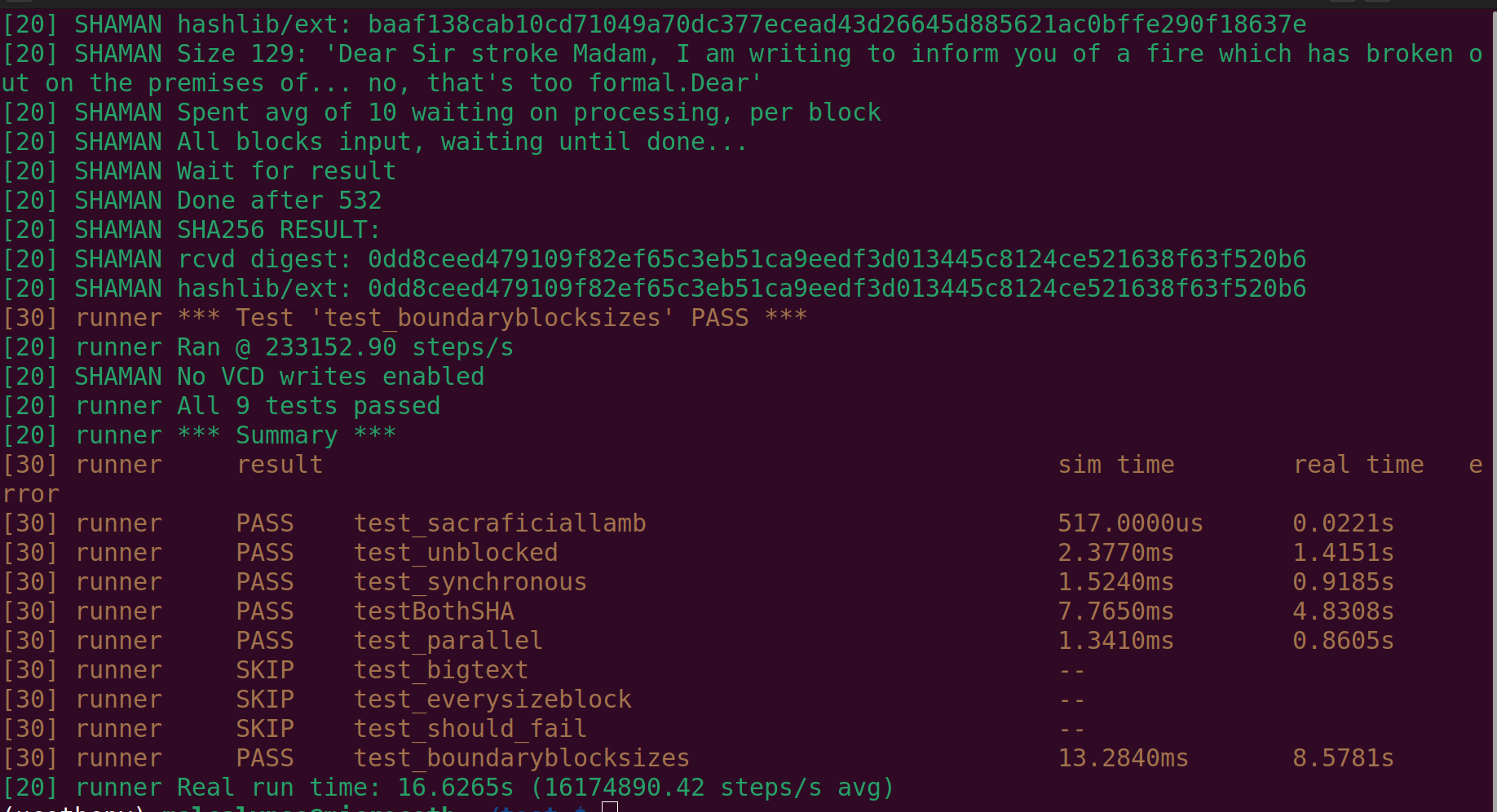
Though not quite as pretty as full cocotb, the tests output logging as usual and provide a summary after the full run
With cocotb, you can test your hardware design while interacting with a simulator. The website mentions that "interfacing with existing infrastructure is easy. Do you want to talk to a golden model in your testbench? Or to real hardware, e.g. an FPGA or a logic analyzer?"
But the solution to getting our ASIC projects into the loop were pretty involved. Rather than recreate a "simulator" which provides a whole VPI API that cocotb can interact with, this code was developped to instead make bringing in the testbench onto the demo boards easy.
A simple USB bridge was created to run tests on the desktop but control real hardware over USB, either
-
projects running on an FPGA, wrapped in a SUB layer to expose the I/O over USB; or
-
external chips, wired to an FPGA with a suitable SUB wrapper to translate USB commands to I/O
More details on this in the SUB section.
All the examples from the Tiny Tapeout SDK run cocotb tests on the RP2040 and interact with actual projects on the ASICs. These were ported in from those used during Verilog development of the projects, and remain mostly as-is.
Using the SUB, to talk to projects through an FPGA over USB (either within the FPGA or an external chip through the FPGA) things are slower than in desktop sim, but still 10x faster than on the RP2040.
On the Pico, tests run successfully but, since we are manually toggling the clock(s) behind the scenes from micropython SDK, the cost of one step is pretty expensive.
A "step" has a duration of 1/2 the (fastest) started clock's period, in simulator time. On the RP2040, in real time this one step winds up consumming about 1.6ms.
So, if the simulation had a 1MHz clock and is waiting on a Timer for 1 ms, that will be 1000 clock cycles, or 2000 times the clock signal is toggled, i.e. steps. Hence, you'll be waiting on this chunk of simulation to complete for over 3 seconds.
On the desktop, a single step is much faster--on the order of 6us on my machine right now, so the same sim would only take about 13ms. The bottleneck on desktop will always be the hardware bridge you are interacting with to control and observe the hardware, whether its libiio, SWV, plain old serial or whatever.
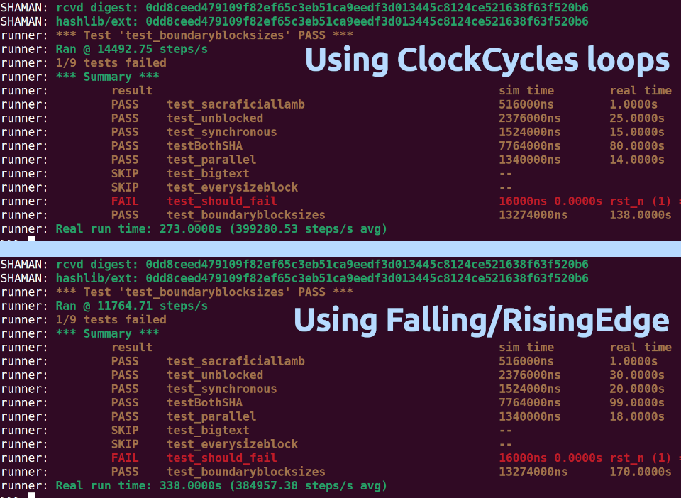
Also of note, awaiting RisingEdge and FallingEdge are slower still, by a good margin (like 20% or so)--the advantage of these are:
-
simplicity: it's a single
await RisingEdge(dut.target_signal)vs a loop where you manually clock and check the signal -
multi-clock support: no matter how many clocks are configured in the system, they'll all tick as appropriate.
but if you have a need for speed, and are using a single clock source, you might be better off doing something like
while not dut.target_signal.value:
    await ClockCycles(dut.clk, 1)
Here's the same set of tests, run with manual loops as above vs using edge triggers, on a RP2040. You can see the difference in runtime is rather substantial in this testbench
Get it and use it from github, by cloning or from a release, or on the desktop you can do
pip install microcotb
This gives you the libraries but head to the repo for the example tests and code
To get started you need three things:
-
a set of @cocotb.test()
-
a way to interact with your hardware from python
-
an DUT type that translates reads and writes to signals to the actual hardware
-
an instance of the DUT and to call the runner
To dive right in can see a loopback/counter demo you can run right now by doing
$ python examples/dummy/tb.py
...
[20] runner *** Summary ***
[30] runner     result                                           sim time        real time       error
[30] runner     PASS    test_loopback                            2.5900ms        0.0074s
[30] runner     PASS    test_counter                             1.0400ms        0.0025s
[30] runner     PASS    test_edge_triggers                       665.0000us      0.0021s
[30] runner     PASS    test_should_fail                         0.0000ns        0.0003s Failed as expected
[30] runner     SKIP    test_will_skip                           --
[30] runner     PASS    tmout/t=50/clk_period=12                 54.0000us       0.0003s
[30] runner     PASS    tmout/t=50/clk_period=10                 50.0000us       0.0003s
[30] runner     PASS    tmout/t=50/clk_period=60                 60.0000us       0.0002s
[40] runner     FAIL    tmout/t=100/clk_period=12                102.0000us      0.0003s Timeout at 102.0000us
[40] runner     FAIL    tmout/t=100/clk_period=10                100.0000us      0.0003s Timeout at 100.0000us
[40] runner     FAIL    tmout/t=100/clk_period=60                120.0000us      0.0003s Timeout at 120.0000us
[40] runner     FAIL    tmout/t=200/clk_period=12                102.0000us      0.0004s Timeout at 102.0000us
[40] runner     FAIL    tmout/t=200/clk_period=10                100.0000us      0.0003s Timeout at 100.0000us
[40] runner     FAIL    tmout/t=200/clk_period=60                120.0000us      0.0002s Timeout at 120.0000us
[30] runner     PASS    test_timer                               1.0000ms        0.0061s
[20] runner Real run time: 0.0217s (355082330.16 steps/s avg)
On the desktop, it's blazingly fast. On uPython, not as much, but it runs, here the factory test project tb
>>> test.run()

# ...
runner: *** Summary ***
runner:         result                                           sim time        real time       error
runner:         PASS    test_loopback                            2.6600ms        2.0000s
runner:         PASS    test_timeout/timer_t=101/clk_period=10   100.0000us      0.0000s Failed as expected
runner:         PASS    test_timeout/timer_t=101/clk_period=125  125.0000us      0.0000s Failed as expected
runner:         PASS    test_timeout/timer_t=200/clk_period=10   100.0000us      0.0000s Failed as expected
runner:         PASS    test_timeout/timer_t=200/clk_period=125  125.0000us      0.0000s Failed as expected
runner:         PASS    test_should_fail                         0.0000ns        0.0000s Failed as expected
runner:         PASS    test_counter                             2.6800ms        3.0000s
runner:         PASS    test_edge_triggers                       744.9999us      1.0000s
runner:         SKIP    test_will_skip                           --
runner: Real run time: 6.0000s (122222.22 steps/s avg)
The main delta here are the libraries included--different name, 'cause different project but doing something like
import microcotb as cocotb
from microcotb.clock import Clock
from microcotb.triggers import RisingEdge, FallingEdge, ClockCycles, Timer
from microcotb.utils import get_sim_time

@cocotb.test()
async def test_loopback(dut):
# ...
The cocotb tests should work pretty much as-is (and if not, get in touch).
So a set of things like
@cocotb.test(timeout_time=100, timeout_unit='us')
async def test_timeout(dut):
    clock = Clock(dut.clk, 10, units="us")
    cocotb.start_soon(clock.start())

    await reset(dut)
    await RisingEdge(dut.is_ready)
Should get you going without much further change to the tests, because all the class names just map.
You'll need some manner of getting and setting signals from the hardware.
This could be directly accessed via micropython, as is the case with Tiny Tapeout. Or it could be over serial, through JTAG, whatever.
For TT demoboards, other than the clock and reset, we have 3 8-bit I/O ports. It looks like this, in verilog. One of those is bidirectional, so it's split into _in and _out:
-
ui_in
-
uo_out
-
uio_in
-
uio_out
So we've got low-level micropython.native accessors like these
With read_bidir_byte, write_bidir_byte etc in hand, we have a way to communicate with the hardware and get/set the signals.
The DUT--device under test--here will need to be created to expose the right interface, in a way that actually gets/sets the hardware.
This library includes a DUT base class for these, which provides some helper functions, setup the _log and things like that.
In order for the DUT to be well behaved in your tests, it needs to provide the same interface as it would in cocotb, namely that you play with dut.attrib.value a lot.
The Tiny Tapeout DUT implementation looks something like this:
class PinWrapper:
    '''
       give bare pins a .value we can assign to
    '''
    def __init__(self, pin):
        self._pin = pin

    @property
    def value(self):
        return self._pin.value()

    @value.setter
    def value(self, set_to:int):
        if self._pin.mode != Pins.OUT:
            self._pin.mode = Pins.OUT
        self._pin.value(set_to)

class DUT(microcotb.dut.DUT):
    '''
        Tiny Tapeout DUT, providing ui_in, uo_out, and uio_(in|out)
    '''
    def __init__(self, name:str='DUT'):

        # get the demoboard singleton
        self.tt = DemoBoard.get()

        # wrap the bare clock pin and reset
        self.clk = PinWrapper(self.tt.clk)
        self.rst_n = PinWrapper(self.tt.rst_n)
        self.ena = NoopSignal(1) # does nothing

        port_defs = [
            ('uo_out',  8, platform.read_output_byte, None),
            ('ui_in',   8, platform.read_input_byte, platform.write_input_byte),
            ('uio_in',  8, platform.read_bidir_byte, platform.write_bidir_byte),
            ('uio_out', 8, platform.read_bidir_byte, None)
            ]
        for p in port_defs:
            self.add_port(*p)
With that DUT, we can run all the TT tests. It's using wrappers and the add_port() method to expose everything in a way that will both interact with the real hardware and go through all the cocotb tests.
Once you have all the above, simply running
    import microcotb as cocotb
    dut = DUT()
    runner = cocotb.get_runner()
    runner.test(dut)
will do it's thing.
The cocotb.test decorator will make the decorated function part of the test bench
It can be used without parameters, e.g.
@cocotb.test()
async def test_clocking(dut):
    dut._log.info("Start")

    clock = Clock(dut.clk, 10, units='us')
    cocotb.start_soon(clock.start())

    await Timer(100, 'us')
The following parameters are supported:
-
name (str), to override default name
-
skip (boolean), to skip the test
-
timeout_time (float) and timeout_unit (str), to support timing out
-
expect_fail (boolean), when true, passes on exceptions raised (fail otherwise)
An example:
@cocotb.test(name='timing out', timeout_time=100, timeout_unit='us')
async def test_timeout(dut):
    clock = Clock(dut.clk, 10, units="us")
    cocotb.start_soon(clock.start())
    await Timer(300, 'us')
This test has a timeout set, and awaits too long. Run like this, the report will show
FAIL timing out Timeout at <TimeValue 100000 ns>
With expect_fail=True, you'd get
PASS timing out Failed as expected
instead.
The equivalent of looping tests with different parameters may be acheived using cocotb.parametrize.
To use this,
-
augment the test definition with parameters
-
specify values to use in cocotb.parametrize()
With a test like:
@cocotb.test(timeout_time=100, timeout_unit='us')
@cocotb.parametrize(
    t=[50, 100, 200],
    clk_period=[12, 10, 60])
async def test_timeout(dut, t:int, clk_period:int):
    clock = Clock(dut.clk, clk_period, units="us")
    cocotb.start_soon(clock.start())
    if t >= 200:
        dut._log.warn(f'Test should FAIL...')
    else:
        dut._log.info(f'Test should pass...')

    await Timer(t, 'us')
You'll get a test run for all combinations of parameters (so 3*3 = 9 test runs in this example).
The output will provide the parameters used for each run, like
    PASS    timing out/t=50/clk_period=12
    PASS    timing out/t=50/clk_period=10
    PASS    timing out/t=50/clk_period=60
    PASS    timing out/t=100/clk_period=12
    PASS    timing out/t=100/clk_period=10
    PASS    timing out/t=100/clk_period=60
    FAIL    timing out/t=200/clk_period=12  Timeout at <TimeValue 102000 ns>
    FAIL    timing out/t=200/clk_period=10  Timeout at <TimeValue 100000 ns>
    FAIL    timing out/t=200/clk_period=60  Timeout at <TimeValue 120000 ns>
You can also use tuples for the parameters, rather than keyword arguments
@cocotb.test(timeout_time=100, timeout_unit='us')
@cocotb.parametrize(
    ('t', [50, 100, 200]),
    ('clk_period', [12, 10, 60])
)
would be equivalent to the above.
As mentioned, the DUT instance needs to be able to both talk with the hardware behind the scenes and to act like the cocotb dut.
If you are simply exposing the pins and ports, doing something like the sample above will work fine.
There are cases where tests you have are safe, in that they do not access any internals of the design, but you've added convenience functionality or renaming to the verilog tb, and your cocotb tests reflect that.
For example, my old neptune testbench looks like this in verilog
// testbench is controlled by test.py
module tb (
    input [2:0] clk_config,
    input input_pulse,
    input display_single_enable,
    input display_single_select,
    output [6:0] segments,
    output prox_select
    );

    // this part dumps the trace to a vcd file that can be viewed with GTKWave
    initial begin
        $dumpfile ("tb.vcd");
        $dumpvars (0, tb);
        #1;
    end

    // wire up the inputs and outputs
    reg  clk;
    reg  rst_n;
    reg  ena;
    // reg  [7:0] ui_in;
    reg  [7:0] uio_in;
    wire [7:0] uo_out;
    wire [7:0] uio_out;
    wire [7:0] uio_oe;

    assign prox_select = uo_out[7];
    assign segments = uo_out[6:0];

    wire [7:0] ui_in = {display_single_select,
                        display_single_enable,
                        input_pulse,
                        clk_config[2], clk_config[1], clk_config[0],
                        1'b0,1'b0};

   /* ... */
and my cocotb tests use the nicely named input_pulse (a bit), clk_config (3 bits), etc.
The first option would be to re-write all the cocotb.test() stuff to use only ui_in and such. Yuk.
Rather than do all that work, and have ugly tt.ui_in.value[5] stuff everywhere as a bonus, you can extend the DUT class to add in wrappers to these values.
To do this, you just derive a new class from microcotb.dut.DUT, create the attributes using add_bit_attribute or add_slice_attribute (for things like tt.ui_in[3:1]).
In my neptune case, this looks like:
# using the ttboard extension of the DUT as the
# baseclass, which already provides ui_in, uo_out, etc
import ttboard.cocotb.dut

class DUT(ttboard.cocotb.dut.DUT):
    def __init__(self):
        super().__init__('Neptune')
        self.tt = DemoBoard.get()
        # inputs
        self.add_bit_attribute('display_single_select', self.tt.ui_in, 7)
        self.add_bit_attribute('display_single_enable', self.tt.ui_in, 6)
        self.add_bit_attribute('input_pulse', self.tt.ui_in, 5)
        self.add_slice_attribute('clk_config', self.tt.ui_in, 4, 2) # tt.ui_in[4:2]
        # outputs
        self.add_bit_attribute('prox_select', self.tt.uo_out, 7)
        self.add_slice_attribute('segments', self.tt.uo_out, 6, 0) # tt.uo_out[6:0]
Using that class to construct my dut, things like
    pulseClock = Clock(dut.input_pulse, 1000*(1.0/tunerInputFreqHz), units='ms')
    cocotb.start_soon(pulseClock.start())
    # or
    val = int(dut.segments.value) << 1
will justwork(tm) in the tests.
More info and some demonstrations coming shortly, keep an eye out here and on my youtube channel.
This library is release under the LGPL. See the LICENSE files for details. Certain portions were adapted from cocotb (namely found in microcotb.types) to run on uPython and extend them, and are
Copyright cocotb contributors
and under the
Licensed under the Revised BSD License, see LICENSE for details. SPDX-License-Identifier: BSD-3-Clause
See individual files.


