DeepSleep support for up to 1 day (i.e., 86,400 seconds) (e.g., if used with KNX) (DeepSleepTime).
The ESP8266 has a limitation of a maximum of ~71 minutes DeepSleep. To overcome the limitation, a short wake-up is performed - the device will wake up every hour for <0.3 seconds until the DeepSleep time is reached. The remaining DeepSleep time is decremented, and the device is then put back in DeepSleep again. The remaining time is stored in RTC memory. As long as the device is powered (e.g., via the battery), this should work fine. Flash memory is not used because of how often this has to occur (every hour) and the time it takes for the flash to be ready takes much longer than the total time to write to the RTC.
DeepSleepTime sets the time the device remains in DeepSleep before it returns to full operating mode. Once the command is issued, the DeepSleep cycle commences. During DeepSleep, the device is effectively off and, as such, it is not possible to modify DeepSleepTime without exiting DeepSleep.
!!! example
With DeepSleepTime 3600, the device will wake up exactly every hour (e.g., 8:00am, 9:00am, ...). If you define DeepSleepTime 86400 (i.e., 60*60*24), it will wake-up exactly at 0:00 UTC time - not your local time. If you define DeepSleepTime 600, it will wake-up every 10 minutes (e.g., 8:00, 8:10, 8:20, ...).
!!! warning Please be aware that the minimum DeepSleep time is 10 seconds.


The following GPIOs CANNOT be used for the purpose of temporarily disabling DeepSleep as described above:
- GPIO16 (because it is connected to RST),
- GPIO15 (because of an existing on-board pull-down resistor),
- GPIO0 (because pulling it down at wake up will enter serial bootload mode).
All others GPIO should be acceptable.
An interresting use-case is to disable DeepSleep when external power (USB, PSU, solar panel...) is applied to the device using a transistor.

If the device is not (easily) accessible, methods can be used to disable the DeepSleep loop without physical access.
Send a retained DeepSleepTime 0 command to your device. As the message is retained in the MQTT broker, the device will receive it as soon as it connectes to the MQTT broker.
!!! example "Example: Sending from another Tasmota"
In another Tasmota console you can type the following command:
Publish2 cmnd/%topic%/DeepSleepTime 0
To clear the retained message, once your device is out of DeepSleep, use:
Publish2 cmnd/%topic%/DeepSleepTime
!!! Example "Example: Sending using mosquitto utilities"
Command to send a retained message:
mosquitto_pub -t "cmnd/myDeviceTopic/DeepsleepTime" -r -m "0"
Remove retained message
mosquitto_pub -t "cmnd/myDeviceTopic/DeepsleepTime" -r -n
You can alsosend retained message or clear them with other MQTT tools: MQTT Explorer, ....
Once you have made your configuration change, you will need to re-enable DeepSleep mode using DeepSleepTime command.
Configure a settable flag in your home automation hub (e.g., Node-Red, openHAB, Home Assistant). The flag should subscribe to the tele/%topic%/LWT topic for the payload Online. Alternatively, if testing the payload value is not easy, subscribe to the topic tele/%topic%/STATE which is the 2nd topic on which the device publish right after waking-up.
The moment a message is received on this topic, the automation can publish a message to topic cmnd/%topic%/DeepSleepTime with payload 0. This will cause the device to disable DeepSleep and allow maintenance such as firmware updates to be performed without having an unexpected DeepSleep event. Send the DeepSleepTime 0 command ==only once==.
Once device maintenance is completed, place it back into DeepSleep mode using original configuration.
!!! tip "If you're having issues after wakeup from sleep"
Make sure bootloop detection is off SetOption36 0. See issue #6890
The following triggers can be used to execute commands upon wake-up or right before entering DeepSleep:
Power1#Boot: is the earliest trigger. But valid only if you have aRelayoutput defined.Switch1#Boot: is the next trigger, also occur very early in the boot process. But valid only if you haveSwitchinput defined.System#Boot: is occuring later in the Tasmota boot process but is always available.SYstem#Save: is occuring right before a restart or before entering DeepSleep.
For exemple the ruleset below turn on power right after Tasmota started, and turn it off just before entering DeepSleep
Rule1 ON Power1#Boot DO Power on ENDON ON System#Save DO Power off ENDON
Sequence is then as follow (only key lines are shown):
00:00:00.085 CFG: Loaded from File, Count 122
00:00:00.095 Project tasmota demo-sensor Version 9.5.0(tasmota-sensors)
00:00:00.105 RUL: POWER1#BOOT performs "Power ON"
00:00:00.109 RSL: POWER = {"POWER":"ON"}
00:00:00.111 RSL: POWER = ON
00:00:04.454 WIF: Connecting to AP1 DEMOAP Channel 1 BSSId XX:XX:XX:XX:XX:XX in mode 11n as demo-sensor...
00:00:05.756 WIF: Connected
00:00:06.008 HTP: Web server active on dev-4119 with IP address 192.168.168.199
15:03:40.010 MQT: Attempting connection...
15:03:40.024 MQT: Connected
15:03:40.028 MQT: tele/demo-sensor/LWT = Online (retained)
15:03:40.032 MQT: cmnd/demo-sensor/POWER =
15:03:40.047 MQT: stat/demo-sensor/POWER = {"POWER":"ON"}
15:03:40.050 MQT: stat/demo-sensor/POWER = ON (retained)
15:03:44.472 MQT: tele/demo-sensor/STATE = {"Time":"2021-06-27T15:03:44+02:00","Uptime":"0T00:00:13","UptimeSec":13,"Heap":28,"SleepMode":"Dynamic","Sleep":50,"LoadAvg":19,"MqttCount":1,"POWER":"ON","Wifi":{"AP":1,"SSId":"DEMOAP","BSSId":"XX:XX:XX:XX:XX:XX","Channel":1,"Mode":"11n","RSSI":86,"Signal":-57,"LinkCount":1,"Downtime":"0T00:00:07"}}
15:03:44.500 MQT: tele/demo-sensor/SENSOR = {"Time":"2021-06-27T15:03:44+02:00","Switch1":"OFF","Switch2":"ON"} (retained)
15:03:44.515 RUL: SYSTEM#SAVE performs "Power OFF"
15:03:44.524 MQT: stat/demo-sensor/POWER = {"POWER":"OFF"}
15:03:44.527 MQT: stat/demo-sensor/POWER = OFF (retained)
15:03:44.539 MQT: stat/demo-sensor/DEEPSLEEP = {"DeepSleep":{"Time":"2021-06-27T15:04:00","Epoch":1624799040}}
15:03:47.433 APP: Sleeping
When writing a driver for a sensor, if the sensor supports a low power mode, it is a good practice to set the sensor in such low power mode in the FUNC_SAVE_BEFORE_RESTART handler. When Tasmota will restart at next wake-up, sensor will be automatically re-initialized.
Exemple from xsns_09_bmp.ino:
#ifdef USE_DEEPSLEEP
      case FUNC_SAVE_BEFORE_RESTART:
        BMP_EnterSleep();
        break;
#endif // USE_DEEPSLEEP
In general you can also execute any command or special script ==BEFORE== device goes into DeepSleep using handler FUNC_SAVE_BEFORE_RESTART as a predefined hook to implement your own procedure. This requires you to code your own function and self-compile custom firmware.
If all requirements (Wifi, NTP time synchronization, MQTT broker connection and TelePeriod) are not met, the device will stay awake while trying to attain the remaining requirements. On battery powered devices this behavior is undesirable because it will quickly deplete the battery. To avoid this when these requirements cannot be met, put the device back into DeepSleep for an hour. Do this through a rule that will be triggered 30 seconds after reboot and sends the device into deepsleep for an hour.
Rule1
  ON Dimmer#Boot DO RuleTimer1 30 ENDON
  ON Rules#Timer=1 DO DeepSleepTime 3600 ENDON

Rule1 ONLet's assume you have set DeepSleepTime 3600 (one hour) and TelePeriod 300 (five minutes). The device will first wake at 8:00 am. The device will boot and connect Wi-Fi. Next, the correct time must be sync'ed from one of the NTP servers. Now the device has all prerequisites for going into DeepSleep.
DeepSleep is then triggered at the TelePeriod event. In this example, it will occur after five minutes. Telemetry will be collected and sent (e.g., via MQTT). Now, DeepSleep can happen. First, Offline is published to the LWT topic on MQTT. It then calculates the new sleeping time to wake-up at 9:00 am (3600 seconds after the last wake-up). At 9:00 am this same sequence of events happens again.
If you want to minimize the time that the device is in operation, decrease TelePeriod down to 10 seconds. This period of time is counted ==after== MQTT is connected. Also, in this case, the device will wake up at 9:00 am even if the uptime was much smaller. If the device missed a wake-up it will try a start at the next event - in this case 10:00 am.
Not all GPIO behave the same during DeepSleep. Some GPIO go HIGH, some LOW, some FOLLOW the relay but work only on FET transistors. As soon as current flows they go LOW. I use one GPIO to trigger a BC337 transistor to switch OFF all connected devices during DeepSleep.
Findings:
| Pin | GPIO | Behavior |
|---|---|---|
| D0 | 16 | Excluded due to use as wake-up pin |
| D1 | 5 | KEEP STATE, go LOW if resistance to ground < infinite |
| D2 | 4 | KEEP STATE, go LOW if resistance to ground < infinite |
| D3 | 0 | HIGH |
| D4 | 2 | HIGH |
| D5 | 14 | HIGH, go LOW if resistance to ground < infinite |
| D6 | 12 | HIGH, go LOW if resistance to ground < infinite |
| D7 | 13 | HIGH, go LOW if resistance to ground < infinite |
| D8 | 15 | LOW |
(logging level 4)
When MQTT connects at 13:08:38, this sets the system to READY.
13:08:43 MQT: tele/tasmota/INFO3 = {"RestartReason":"Deep-Sleep Wake"}
13:08:44 APP: Boot Count 3
13:08:44 CFG: Saved to flash at F4, Count 96, Bytes 3824
In the context of DeepSleep, maintaining a device boot count is not relevant. When DeepSleep is enabled, boot count will not be incremented. This avoids excessive flash writes which will deteriorate the flash memory chip and eventually cause the device to fail. Boot count incrementing can be enabled using SetOption76.
In this example, TelePeriod is 10. Therefore when it is reached, telemetry reporting occurs.
13:08:48 MQT: tele/tasmota/STATE = {"Time":"2019-09-04T13:08:48","Epoch":1567595328,"Uptime":"0T00:00:14","UptimeSec":14,"Heap":24,"SleepMode":"Dynamic","Sleep":50,"LoadAvg":20,"MqttCount":1,"Wifi":{"AP":1,"SSId":"MyWLAN","BSSId":"AA:FF:AA:AA:AA:AA","Channel":11,"RSSI":100,"LinkCount":1,"Downtime":"0T00:00:08","DeepSleep":300,"Heap":25160}}
13:08:48 MQT: tele/tasmota/SENSOR = {"Time":"2019-09-04T13:08:48","Epoch":1567595328,"ANALOG":{"A0":8}}
Date and time is set, status and telemetry sent. Now start shutdown procedure.
First, send MQTT offline.
13:08:48 MQT: state/sonoff/LWT = Offline
DeepSleep is 300 seconds. Therefore +-30 sec is allowed as deviation between proposed wake-up time and real wake-up time. Reporting in 0.1sec. In this case wake-up was one second late.
13:08:48 Timeslip 0.1 sec:? -300 < -10 < 300
If the error is in the range, this is tagged as a normal wake up where drift can be recalculated
13:08:48 Normal deepsleep? 1
Recalculate a new drift that is a multiplier for the next wake-up in 1/10000. In this case, the multiplier is 1.0257
13:08:48 % RTC new drift 10257
And for information: New target wake-up time
13:08:48 Next wakeup 2019-09-04T13:10:00
Based on run time and the error in the last loop, a new sleeping time will be calculated. This will be multiplied by the deepsleep_slip and, ideally, the device will wake up at the time above.
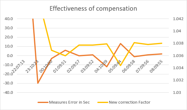
13:08:48 Sleeptime 285 sec, deepsleep_slip 10257
The effectiveness of the compensation can be seen here. Instead of typically 160-200 seconds, most times it is better than 10 seconds in a one hour DeepSleep cycle.
In some applications, it is interresting to adjust the DeepSleep period to the level of the battery. For this, we consider that:
- the battery level is measured by the ESP ADC with the appropriate voltage divider,
- the Tasmota ADC mode is set to Range mode,
AdcParams 6has been used so the range value represent the battery voltage in millivolts
The below graph represent the adaptation paths we want to follow to adjust DeepSleepTime: one path while the level is dropping, another path while the level is rising.

To implement this in Tasmota we can use Rules. As Rules do not provide an AND operator,
we also need the optional IF feature. This requires to compile a customized firmware
with the following items in user_config_override.h:
#define USE_RULES
#define SUPPORT_IF_STATEMENT
First, we need to know the current value of DeepSleepTime. Values for internal settings are not
available as %variable% but they can generally be obtained by sending the command and capturing
the result with a rule. To get the current value of DeepSleepTime, we need a trigger early in the
boot process. For example Wifi#Connected.
Our first rules to get the current DeepSleepTime into %var1% would be:
ON Wifi#Connected DO Backlog DeepSleepTime ENDON
ON DeepSleepTime#Data DO var1 %value% ENDON
The best moment to compare the batery level and decide if it is necessary to change the DeepSleepTime
is right after the TelePeriod SENSOR message has been sent, which is just before Tasmota calculate
the next wake-up time. So we can use tele-ANALOG#Range as a
trigger for our rules. Using BREAK allows to compare the trigger only to the upper value of the
segment and stop further rules evaluations if the comparison is met. In the rule statement for a
given battery level, we compare the current value of DeepSleepTime (which is %var1%) with the value
we vant (given by the graph). If the current value is lower than the value we want, we are on the
decreasing path and we can apply the new value. If the current value is greater than the value we want,
we are on the rising path and we can apply the new value.

All above can be set into Rule1. As it is a long command, it may be necessary to enter the rule
in 2 parts (note the usage of the +) :
Rule1 on Wifi#Connected do backlog deepsleeptime endon on deepsleeptime#data do var1 %value% endon on tele-Analog#Range<3450 do if (%var1%<3600) deepsleeptime 3600 endif break on tele-Analog#Range<3650 do if (%var1%<1800) deepsleeptime 1800 endif break
Rule1 +on tele-Analog#Range<3800 do if (%var1%<900) deepsleeptime 900 elseif (%var1%>1800) deepsleeptime 1800 endif break on tele-Analog#Range<4000 do if (%var1%>900)deepsleeptime 900 endif break on tele-Analog#Range>=4000 do if (%var1%> 600) deepsleeptime 600 endif endon
Don't forget to enable using Rule1 1