DS18x20 driver supports DS18B20, DS18S20, DS1822 and MAX31850 1-Wire digital temperature sensors.
| DS18b20 | ESP266 |
|---|---|
| 1 GND | GND |
| 2 Data | GPIO 0..15 |
| 3 VCC | 3.3v |
!!! Warning "Warning: DS18x20 is not supported on GPIO16"
You need to connect a 4.7K pullup resistor from data to 3.3V.

In the Configuration -> Configure Module page assign:
- GPIOx to
DS18x20
Shelly dual pin mode is also supported by additional pinassignment:
- GPIOx to
DS18x20-o
After validation by SAVE button press, a reboot is done and webUI displays temperature measured.
Sensor sends a tele/%topic%/SENSOR JSON reponse:
{"Time":"2021-07-17T17:29:51","DS18B20":{"Id":"000003287EF1","Temperature":24.7},"TempUnit":"C"}SetOption74 may be used to enable/disable internal pullup when using a single DS18x20 sensor (for multiple sensors, you have to use an external pullup resistor).
SetOption126 Enable arithmetic mean over teleperiod for JSON temperature for DS18x20 sensors.
TempRes Temperature sensor resolution: 0..3 = maximum number of decimal places.
TempOffset can be used for calibrating the measured temperature. This setting affects all temperature sensors on the device.
Tasmota supports multiple DS18x20 sensors connected to a single ESP8266 chip using a single GPIO (multiple DS18x20 GPIO are not supported). The default maximum is set to 8 (driver code). It is possible to override this number in user_config_override.h by adding a line with #define DS18X20_MAX_SENSORS <new-value> (ESP8266 only). However one should take into account that:
- Display on the console is limited and SENSOR log will be truncated above 11 DS18x20.
- MQTT buffer length is limited and SENSOR message will be truncated above 18 DS18x20.
- Even less if other sensors are attached to the ESP device and present in the SENSOR message.
- 1-wire has been designed to be a board-bus, not to run through long distances across a whole house. At minimum, use a shielded cable.
!!! note If you increase the value above default, you are on your own. No support will be provided.

Every sensors will get a unique ID used in webUI and MQTT telemetry.
{"Time":"2021-01-02T09:09:44","DS18B20-1":{"Id":"00000566CC39","Temperature":13.3},"DS18B20-2":{"Id":"0000059352D4","Temperature":1.2},"DS18B20-3":{"Id":"000005937C90","Temperature":22.5},"TempUnit":"C"}There are some compile options (driver code):
[USE_DS18x20_RECONFIGURE] When sensor is lost keep retrying or re-configure
[DS18x20_USE_ID_AS_NAME] Use last 3 bytes for naming of sensors

Pinout when looking at the flat side of the TO-92 package sensor: GND, Signal, VDD. Pinout of the wired sensor: black: GND; yellow or white: Signal, red: VDD
!!! danger BEWARE OF MANY VISUALLY SIMILAR BOARDS TO THIS RELAY BOARD but different schematics
Some modules have culprits:
- "CH_PD" is not set to HI (3.3V) as actually required. Usually this is done with a 10K resistor or directly to 3.3V, I have connected directly to the 3.3V
- A resistor (R2 10k) which is connected between the terminal GPIO0 to ground. This ensures that the GPIO0 is always pulled to ground, which actually places the ESP-01 in program mode (flashing). To make the module working it is necessary to remove (solder out).
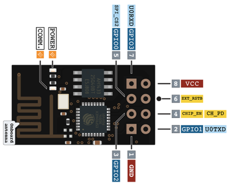
Connect DS18B20 to the GPIO2 (see diagram below - soldering not necessary, it is possible to put the wires and the resistor directly in to the female part of the connector together with ESP 01S module pins)
After flashing, set up Tasmota (see images below):
- "Generic module"
- GPIO0 as Relay 1
- GPIO2 as DS18x20
Retrieving the temperature via HTTP
http://tasmota-ip/cm?user=<USER>&password=<PASS>&cmnd=status%2010
The temperature information will put published by MQTT to the stat/%topic%/STATUS10 in the format of:
{"StatusSNS":{"Time":"2021-07-17T17:34:43","DS18B20":{"Id":"000003287EF1","Temperature":23.6},"TempUnit":"C"}}
The following trigger events are supported for use in Rules:
Single sensor attached:
ON DS1820#Temperature DO <command> ENDON
Multiple sensors attached:
  ON DS1820_1#Temperature DO <command> ENDON
  ON DS1820_2#Temperature DO <command> ENDON
  ON DS1820_3#Temperature DO <command> ENDON
  ON DS1820_..#Temperature DO <command> ENDON
Example:
ON DS1820_1#Temperature!=%Var1% DO backlog publish espTempertature/sensor/DS1820_1/data %value%; Var1 %value% ENDON